


Tesla Polyphase Induction Motors: Design, Operation, and Applications
Induction motors dominate the AC landscape, accounting for roughly 90% of industrial machines. Their resilience and straightforward construction make them the go-to choice for heavy‑duty drives.
In 1883 Nikola Tesla laid out the fundamentals of the polyphase induction motor. By 1888 he had built a 0.5‑hp (400 W) prototype, which he later sold to George Westinghouse for $65,000—an investment that spurred the widespread adoption of AC power.
Large industrial drives—those exceeding 1 hp (1 kW)—are almost always polyphase induction motors. “Polyphase” refers to the presence of multiple windings per motor pole, energized by sine waves that are phase‑shifted in time. In practice this is typically two or, more commonly, three phases; the vast majority of commercial motors are three‑phase devices.
Unlike a brushed DC motor, an induction motor uses the stator windings to generate a rotating magnetic field that induces currents in the rotor conductors, creating a transformer‑like secondary that produces torque.
AC Induction Motor Construction
The core of an induction motor is a simple two‑part assembly: a rotor (the armature) and a stator that houses the windings. The stator is connected to a polyphase supply, as illustrated in the diagram below.
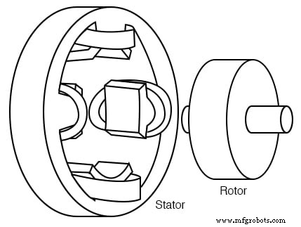
Tesla polyphase induction motor
The stator windings are arranged in pairs—one pair per phase. Each pair consists of two coils in series, one representing a north pole and the other a south pole. In a two‑phase motor, the second pair is positioned 90° in space relative to the first, and the corresponding AC supply is phase‑shifted by 90°. Tesla’s original motor employed a two‑phase alternator as the power source.
Early motors featured salient poles, a design still used for sub‑fractional horsepower units (<50 W). For larger motors, winding slots in the stator laminations reduce torque ripple and improve efficiency.
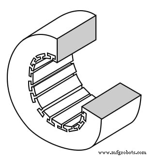
Stator frame with winding slots
The stator laminations are thin, insulated steel sheets with precisely cut slots. A stack of these sheets is secured by end screws that also serve as the end housings.
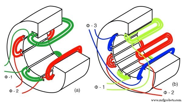
Stator with 2‑phase and 3‑phase windings
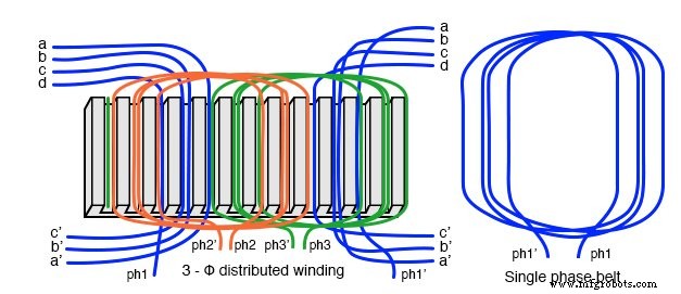
In practice, each pole winding is distributed across many smaller slots—forming a phase belt—that smooths the magnetic field and reduces harmonic distortion. Edge slots may contain windings from two phases, allowing the phase belts to overlap.
The rotor’s simplicity is a key advantage. It consists of a steel laminated core with an embedded copper or aluminum squirrel‑cage, as shown below. The absence of brushes or commutators eliminates arcing, wear, and the need for regular maintenance.
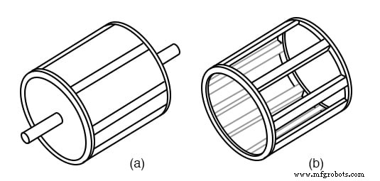
Laminated rotor and squirrel cage
To reduce torque ripple, the squirrel‑cage conductors may be skewed or twisted relative to the shaft, ensuring that the magnetic field is not perfectly aligned with the stator slots.
Both rotor and stator cores use insulated laminations coated with oxide or varnish to curb eddy currents, while the steel alloy is chosen for its low hysteresis losses.
Theory of Operation
An induction motor operates on the principle of a rotating magnetic field. When a time‑shifted sinusoidal voltage is applied to the stator windings, a magnetic field that rotates at the line frequency is produced. This field induces currents in the rotor conductors, which in turn generate their own magnetic field. The interaction between the stator and rotor fields produces torque.
In a simple analogy, a rotating permanent magnet induces currents in a conductive disc. According to Lenz’s Law, the induced magnetic field opposes the motion of the magnet, causing the disc to lag behind. The lag—known as slip—creates the necessary torque to drive a load.
For a two‑phase motor, the stator windings are 90° out of phase, creating a circular rotating field. Three‑phase motors employ windings 120° apart, producing an even smoother rotation.
When the rotor is unloaded, it turns at the synchronous speed (the speed of the rotating field). As a load is applied, the rotor slows, increasing slip, which in turn raises the induced current and torque until the motor reaches its operating point.
Full Speed and Synchronous Speed
The synchronous speed (Ns) is given by:
Ns = 120·f / P
where f is the supply frequency (Hz) and P is the total number of poles. For a 60 Hz supply and a 6‑pole motor (three pole pairs), Ns equals 3600 rpm. Reducing the pole count halves the speed, while doubling the poles halves the synchronous speed.
Torque and Slip Characteristics
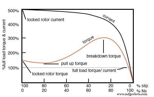
At startup, the rotor is stationary and the stator field rotates at synchronous speed. The resulting maximum induced current produces the locked‑rotor torque (LRT), typically 1.5–3.5 times the full‑load torque (FLT). The corresponding locked‑rotor current (LRC) can reach 5–14 × the full‑load current (FLC).
As the rotor accelerates, slip decreases, and the induced rotor frequency (fr) is:
fr = s · f
where s = (Ns – N) / Ns. For a 5% slip on a 50 Hz supply, fr is only 2.5 Hz—reflecting the small difference between the field and rotor speeds.
Torque versus slip curves typically show peak torque (breakdown torque) at 80–100% of synchronous speed, with LRT occurring at 0% slip. Continuous operation is safe below the rated torque; exceeding it for prolonged periods can damage the motor.
NEMA and IEC Motor Classes
Standard motor classes are defined to match torque curves with specific load types. The National Electrical Manufacturers Association (NEMA) and the International Electrotechnical Commission (IEC) provide equivalent classes:
- Class B / IEC N – Default for pumps, fans, and machine tools; LRT 150–170 % FLT.
- Class A – Higher LRT and dropout torque; suitable for injection‑molding machines.
- Class C / IEC H – LRT 200 % FLT; used for conveyors, crushers, and compressors.
- Class D – Highest starting torque with low current due to high slip; ideal for variable‑speed applications like elevators.
- Class E – Higher efficiency variant of Class B.
- Class F – Low LRC and breakdown torque; best for constant‑speed, easily started loads.
Except for Class D, all motors operate at 5% slip or less at full load.
Power Factor and Efficiency
Large, fully loaded, high‑speed induction motors can achieve power factors (PF) as high as 0.90. At ¾ full load, PF may reach 0.92. Small, low‑speed motors can have PF as low as 0.50, with starting values between 0.10 and 0.25.
Efficiency trends mirror load: large 3‑phase motors can reach 95 % at full load, while 90 % is typical. Efficiency peaks near 75 % of rated torque, dropping slightly at 50 % and further at 25 %. Motors are often oversized to guarantee reliable starting and operation across all loads.
Static phase converters and self‑starting designs enable three‑phase motors to run on single‑phase supply, but require careful capacitor sizing and load management.
Induction Motors as Generators
When driven above synchronous speed—i.e., with negative slip—an induction motor becomes an induction generator. The rotor then induces a voltage back into the stator, feeding power into the grid. This mode is ideal for wind turbines and other variable‑speed drives, offering inherent slip protection and simplifying control.
However, induction generators require a live 50 Hz or 60 Hz supply for excitation and are unsuitable as standalone backup power sources.
Starting and Speed Control
Large motors can draw 500–1400 % of full‑load current at start, causing voltage sag. Motor starters—either autotransformers or solid‑state devices—reduce the initial voltage, limiting the current to 200–500 % of full load. For motors above 50 kW, phase‑controlled or electronic starters are standard.
Electronic variable‑speed drives adjust both frequency and voltage, maintaining torque while preventing magnetic saturation. Control strategies include scalar, vector, and direct torque control, each offering varying degrees of precision and complexity.
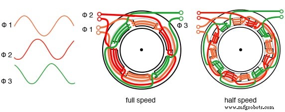
Multiple Field Windings and Variable Voltage
By incorporating multiple pole windings, a single motor can operate at distinct synchronous speeds (e.g., 1800 rpm for 4‑pole and 3600 rpm for 2‑pole). Switching between these configurations is achieved by re‑routing the stator windings.
For fan drives and similar applications, reducing line voltage is a simple way to lower speed. Modern drives use electronic modulation to vary frequency and voltage simultaneously, providing smooth speed control without sacrificing torque.
Linear Induction Motors
Unrolling the circular rotor and stator turns a conventional induction motor into a linear induction motor (LIM). LIMs offer high acceleration and can generate magnetic levitation, making them candidates for high‑speed transport and advanced launch systems. Though cost remains high, LIMs are slated to replace steam‑driven catapults on future naval carriers.
Key Takeaways
- A polyphase induction motor features laminated stator windings and a squirrel‑cage rotor.
- Three‑phase motors self‑start, producing torque through rotor slip.
- Motor starters reduce inrush current while preserving starting torque.
- Three‑phase motors can run on single phase with a static phase converter.
- Multiple field windings enable discrete speed settings.
- Modern electronic drives provide precise speed control across a wide range.
Related Resources
Industrial Technology
- Build a Permanent Capacitor Split-Phase Induction Motor – Step‑by‑Step Guide
- Build a Large-Scale AC Permanent Split‑Capacitor Induction Motor
- Designing Polyphase AC Motors: Fundamentals and Practical Startup Techniques
- Stepper Motors: Types, Characteristics, and Practical Applications
- Brushless DC Motors: Design, Construction, and Advanced Applications
- Wound‑Rotor Induction Motors: Design, Advantages, and Variable‑Speed Applications
- Understanding Single‑Phase Induction Motors: Types, Operation, and Efficiency Improvements
- Specialized Motors: Shaded‑Pole, Servo, Hysteresis, and Eddy‑Current Clutch Applications
- Understanding AC Commutator Motors: Design, Types, and Applications
- Extending Motor Life: Expert Maintenance Tips