


Build a Large-Scale AC Permanent Split‑Capacitor Induction Motor
In this detailed guide you’ll learn how to construct a sizeable permanent split‑capacitor induction motor that can serve as an engaging, hands‑on exhibit. The design is simple yet demonstrates the core principles of AC induction motors, making it ideal for educators, hobbyists, and engineering students.
Materials & Components
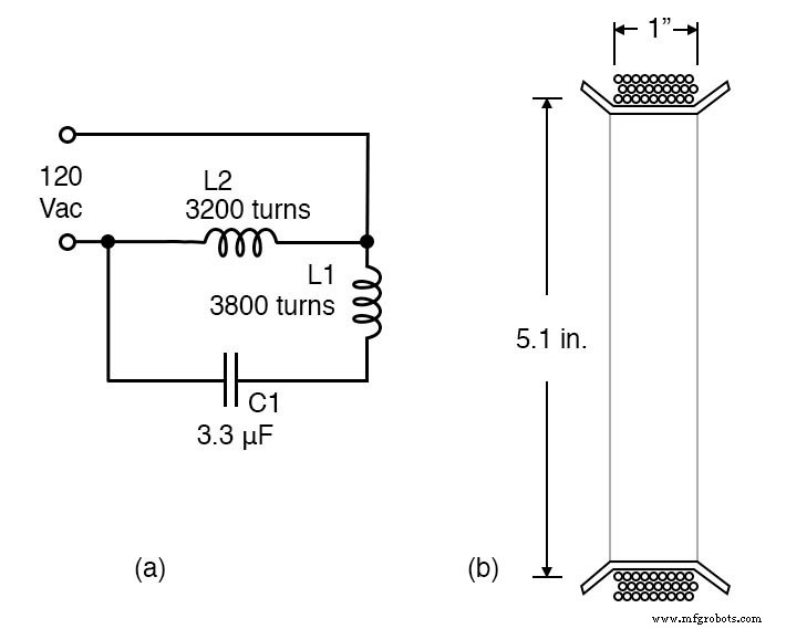
- AC power source: 120 VAC
- 3.3 µF, 120 VAC (or 350 VDC) non‑polarized capacitor
- #33 AWG magnet wire – 2 lb (≈ 3 m)
- Wooden board, 6–12 in. square (or Plexiglas for safety)
- AC line cord with plug
- 5.1‑inch diameter, 3‑liter plastic soda bottle (cut to form)
- Discarded ballpoint pen (pivot)
- Miscellaneous small wood blocks (for mounting)
Learning Objectives
- Assemble a large exhibit‑sized permanent split‑capacitor induction motor.
- Illustrate the inherent simplicity and elegance of AC induction motor design.
Reference Materials
See Lessons in Electric Circuits, Volume 2, Chapter 13: “AC Motors,” “Single‑Phase Induction Motors,” and “Permanent Split‑Capacitor Motor.”
Schematic & Illustration
Construction Steps
1. Prepare the Form
Mark a 1.25‑inch‑wide cylinder on the soda bottle, leaving 0.25‑inch margins at each end. Cut the bottle’s outer edges to create the winding zone. Space 1‑inch‑interval cuts at each end to allow the margin to fold 90° and hold the wire.
2. Wind the Secondary (L2) Coil
Wrap ~3800 turns of #33 AWG wire over the 1.25‑inch zone. If counting turns is impractical, wind 1/8‑inch thick wire across the one‑inch width and later verify the resistance. Strip enamel from a 1‑inch segment of the free end and from the lead to the spool. Do not cut the spool lead; measure its resistance and calculate the additional turns needed to reach ~894 Ω. Insulate the bare segment with enamel, nail polish, tape, or heat‑shrink tubing, then continue winding and re‑check resistance. Once ~894 Ω is achieved, leave a few inches of wire for the lead, cut it from the spool, and secure the winding with twine or similar material.
3. Wind the Primary (L1) Coil
Wrap ~3200 turns on the 1.0‑inch‑wide form (see illustration (b)). Strip 1 inch of enamel from each lead, splice to heavier gauge insulated hookup wire, solder, and insulate. Secure the splice to the coil body. Repeat for the second coil if desired.
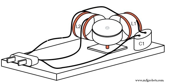
4. Assemble the Motor
Mount the two coils at right angles on the wooden base or movable pallets. Wire L2 across both sides of the 120 VAC line. Connect the capacitor in series with the wider L1 coil to introduce a leading‑phase shift. Verify that no power switch or fuse is present; these will be added in the safety section.
5. Construct the Rotor
Select a ferromagnetic can (e.g., steel vegetable can, fruit‑cake can) or a smaller can lid. Dimple the rotor’s center using an 1/8‑inch nail and a wooden block, or use a ballpoint pen tip as a pivot. Mount the pivot on a movable wooden pedestal. For larger rotors, a longer can offers better balance.
6. Final Wiring & Testing
Double‑check all connections, ensuring bare wires are insulated. Power the circuit without the rotor first; excessive heating in L2 indicates a need for more turns, while overheating in L1 suggests reducing the capacitor value. When the rotor is placed between the coils, it should spin; proximity to the coils increases speed. Experiment with different rotor sizes and positions.
Safety Enhancements for Exhibits
- Cover exposed terminals (e.g., capacitor) with protective shields.
- Add a mains switch and a fuse for overload protection.
- Apply a second insulation layer (e.g., heat‑shrink tubing, Plexiglas enclosure) because enamel alone offers only single‑layer protection.
- Replace wooden parts with fire‑resistant Plexiglas for unsupervised use.
Variations & Advanced Features
- Use #32 AWG wire for easier handling; expect higher current due to lower resistance.
- Swap the 3.3 µF capacitor with a similarly rated part if unavailable; avoid motor‑start capacitors.
- Spin multiple rotors simultaneously by adding a second, smaller rotor near the coil pair.
- Reverse rotation by rotating one coil 180° on movable pallets or wiring a DPDT polarity‑reversing switch to a coil.
Related Worksheets
- AC Motor Theory Worksheet
- AC Motor Control Circuits Worksheet
With these instructions, you can build a robust, educational induction motor that safely demonstrates the fundamentals of AC power and electromagnetism.
Industrial Technology
- Using a Potentiometer as a Rheostat for Simple Motor Speed Control
- Build a Permanent Capacitor Split-Phase Induction Motor – Step‑by‑Step Guide
- Half‑Wave Rectifier Experiment: Build, Measure, and Simulate a Simple AC‑to‑DC Motor Circuit
- Understanding Contactors: Types, Functions, and Overload Protection
- Understanding Ladder Diagrams: Design, Wiring, and Safety in Industrial Control Systems
- Electromagnetic Induction: The Engine of Modern Electricity
- Variable Reluctance Motors: Types, Operation, and Applications
- Tesla Polyphase Induction Motors: Design, Operation, and Applications
- Understanding Single‑Phase Induction Motors: Types, Operation, and Efficiency Improvements
- Running a Three‑Phase Induction Motor from a Single‑Phase Power Supply: Proven Methods and Tips