


Using Commutating Diodes to Protect Inductive Loads
Diodes are widely employed to tame the high‑voltage spikes that arise when current through an inductor is abruptly interrupted—a phenomenon known as inductive kickback.
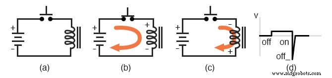
Inductive Kickback Without Protection
Consider the simple circuit shown below. When the push‑button switch closes, current flows from the battery through the coil, building a magnetic field that stores energy. If the switch is then opened, the collapsing magnetic field forces a voltage spike across the coil because the induced emf is proportional to the rate of change of magnetic flux (Faraday’s Law: e = N·dΦ/dt). This reverse‑polarity pulse can reach hundreds of volts, arcing across the switch contacts and dramatically shortening their life.
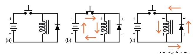
Inductive Kickback With a Commutating Diode
Adding a commutating diode—placed in parallel with the coil—provides a simple and effective solution. The diode is reverse‑biased while the coil is energized, so it does not conduct during normal operation. When the switch opens, the coil’s inductance generates a reverse‑polarized voltage that forward‑biases the diode, allowing the stored energy to circulate safely through the diode instead of arcing across the contacts.
Because the diode’s forward voltage drop (≈0.7 V for silicon) is much lower than the inductive spike, the switch sees only the battery voltage plus a tiny drop, greatly reducing arcing and extending component life.
What Is a Commutating Diode?
In electronic terminology, commutation refers to the reversal of voltage polarity or current direction. A commutating diode—sometimes called a snubber—acts whenever the voltage reverses, such as when an inductor is suddenly de‑energized. It “snubs” the high‑voltage transient by providing a low‑impedance path for the inductive current.
Drawbacks of Using a Commutating Diode
The main trade‑off is that the diode slows the coil’s demagnetization. With the voltage clamped to the diode’s forward drop, the magnetic flux decays more slowly than in an unprotected circuit. While the discharge time remains well under one second, the added delay can be critical for relays and other electromechanical devices that rely on rapid de‑energization.
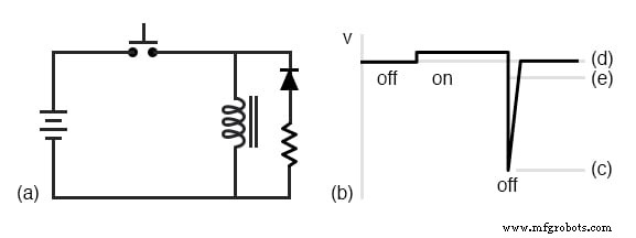
Finding a Balance: Diode Plus Resistor
To achieve a compromise between limiting peak voltage and maintaining a faster decay, a resistor can be added in series with the commutating diode. This allows the induced voltage to rise above the diode’s forward drop, accelerating the magnetic field collapse while still keeping the peak voltage within acceptable limits. The resistor value must be chosen to limit the transient to a level the switch contacts can tolerate.
Key Takeaways
- Inductive kickback can damage switch contacts if left unmitigated.
- A commutating diode safely diverts the induced current, reducing the voltage spike to the diode’s forward drop.
- Using a resistor with the diode speeds demagnetization but increases the transient voltage.
- Choose the protection scheme based on the application’s tolerance for delay and voltage stress.
RELATED WORKSHEETS:
- DC Motor Theory Worksheet
- Miscellaneous Diode Applications Worksheet
Industrial Technology
- Sensitive Voltage Detector: Build a High‑Sensitivity Audio Signal Detector
- Passive Averager and Op‑Amp Summer Circuits: From Averaging to Addition
- Power Supply Circuits: Types, Design Principles, and Performance
- Understanding Power in Electric Circuits: Measurement & Significance
- Voltage Divider Circuits: Mastering Series Resistor Analysis & Potentiometers
- Designing Wattmeters: Leveraging Dynamometer Movements for Accurate Power Measurement
- Understanding Mutual Inductance and Transformers: Principles, Applications, and Key Concepts
- Understanding Inductor Transient Response: Energy, Current, and Voltage Dynamics
- Understanding AC Inductor Circuits: Reactance, Phase Shift, and Power Dynamics
- AC Capacitor Circuits: Capacitive Reactance, Phase Shift, and Power Behavior