


Diode Switching Circuits: From Logic Gates to Analog Control
Diodes are versatile components that can act as fast switches in both digital and analog domains. By biasing a diode forward or reverse, it toggles between a low‑impedance path (forward) and an open circuit (reverse), enabling it to perform logic functions, provide backup power, and control RF resonators.
Digital Logic with Diodes
Historically, diode logic underpinned early computing machines. Although modern processors use CMOS logic, diodes still serve as educational tools and in niche applications where a minimal gate count is desired.
AND Gate
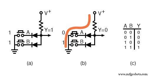
The diagram shows a two‑input AND gate. Each input is either high (≈10 V, logic 1) or low (0 V, logic 0). A series resistor feeds the output Y. When both inputs are high, the output remains at V+ because the resistor dominates. If either input pulls its diode cathode to ground, the output drops to ~0.7 V, the forward drop of the diode. The truth table in the accompanying figure confirms the logical AND behaviour: only when A = 1 and B = 1 does Y stay high.
OR Gate
A two‑input OR gate uses a pair of diodes connected to the same output. When both inputs are low, the resistor pulls Y low. If either input is high, its diode conducts, raising Y to the supply voltage. The truth table illustrates this: any high input yields a high output.
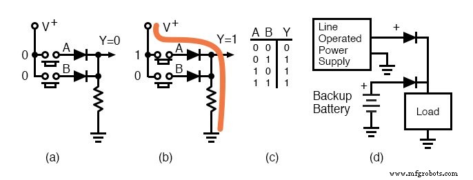
Figure (d) demonstrates a common real‑world use: a backup battery OR‑wired with a mains supply. Diodes in series protect the battery from over‑discharge and prevent back‑feeding when the mains is present. During a power outage, the battery automatically supplies the load.
Analog Switching with Diodes
Reverse‑biased diodes behave like open circuits, while forward‑biased diodes offer low resistance, making them suitable for switching AC signals without disturbing the DC control lines. The following resonant network illustrates this principle.
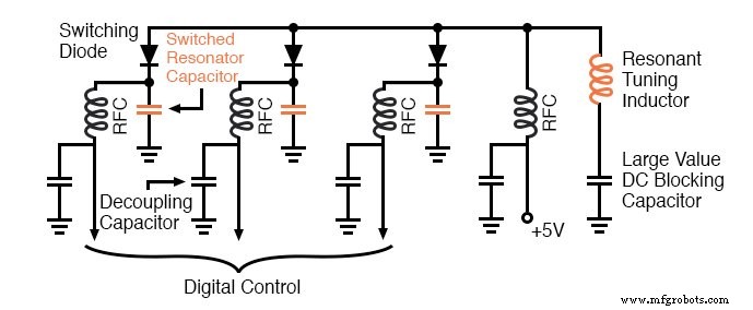
In this setup, a parallel LC resonator is coupled to a set of switched capacitors. Each capacitor is selected by a digital control line that forward‑biases its associated diode. When the control line is low (+5 V through an RF choke and a diode), the capacitor connects in parallel, lowering the resonant frequency. With all controls high, no capacitors are engaged. The RF choke and large DC‑blocking capacitor isolate the RF path from the control circuitry, preventing AC leakage.
At very high frequencies, the parasitic capacitance of reverse‑biased diodes can become significant; PIN diodes are often used instead to achieve lower capacitance and higher isolation.
RELATED WORKSHEETS:
- Basic Logic Gates Worksheet
Industrial Technology
- Foundations of DC Circuits: Understanding Direct Current and Core Electrical Concepts
- Understanding AC Circuits: A Beginner's Guide
- Commutating Diode Experiment: Suppressing Inductive Kickback with a Neon Lamp
- Integrated Circuits: Fundamentals of Digital Logic Gates
- Understanding Clipper Circuits: Theory, Simulation, and Practical Applications
- Crystal and Transistor Radio Circuits: From Basic Detectors to Integrated AM/FM Receivers
- Control Circuits: Fundamentals, Applications, and Best Practices
- Digital Integrated Circuits: Types & Applications
- Essential Semiconductor Device Fundamentals: 6 Key Concepts You Must Master
- Diode Clipping Circuits: An In-Depth Guide to Types and Applications