


Zener Diodes Explained: Voltage Regulation, Design Principles, and Practical Applications
What Is a Zener Diode?
A Zener diode is a specialized rectifying device engineered to tolerate controlled reverse‑breakdown without damage. While ordinary diodes fail when subjected to reverse bias above their breakdown voltage, a Zener diode maintains integrity and offers a stable voltage drop once the reverse voltage reaches its specified Zener voltage. This property makes it invaluable for voltage regulation and reference applications in power supplies, signal conditioning, and protection circuits.
How Diodes Regulate Voltage Drop
When a diode is forward‑biased and placed in series with a resistor across a DC supply, its voltage drop remains remarkably constant—typically around 0.7 V for silicon devices—across a wide range of currents. This behavior follows the exponential diode equation: the current increases sharply with a modest rise in forward voltage, but the voltage itself changes only slightly as current varies. Consequently, the series resistor absorbs most of the supply voltage variation, while the diode maintains a near‑constant drop.
Illustration: 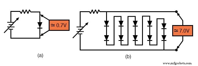
In figure (a), a single 0.7 V diode is used; in figure (b), ten such diodes in series produce a regulated 7.0 V output. If the supply voltage rises, the resistor’s voltage drop increases accordingly, leaving the diode’s voltage largely unchanged, and vice versa.
The Use of Voltage Regulation
Voltage regulation is essential when a circuit requires a stable supply but the source voltage varies, such as with a battery whose voltage degrades over time. By inserting a diode (or a series of diodes) and a resistor, the circuit can provide a fixed voltage to the load while the resistor absorbs supply fluctuations. However, most applications need more than 0.7 V, so multiple diodes are stacked to achieve the desired regulation point.
How Zener Diodes Regulate Voltage
Standard diodes can also exhibit reverse breakdown, but this typically destroys the device. Zener diodes are specially constructed to survive breakdown and maintain a stable voltage—known as the Zener voltage—once the reverse bias reaches that threshold. In reverse bias, the Zener conducts significant current while clamping the voltage across it to its Zener voltage, thus acting as a voltage reference.
Illustration: 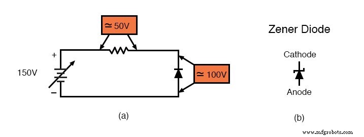
Zener Diode Circuit
Zener diodes are available in a wide range of voltages, from a few volts up to several hundred volts, and are commonly rated at 0.5 W, 1.3 W, or higher. Although their voltage may drift by 5–10 % with temperature, they are precise enough for most regulator circuits. A typical configuration uses a series resistor to limit current and a Zener diode reverse‑biased across the load.
Illustration: 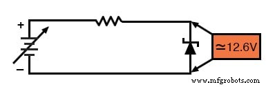
In this example, the Zener voltage is 12.6 V. When the supply voltage exceeds 12.6 V, the Zener conducts and keeps the output at 12.6 V, as long as the power dissipation remains below the diode’s rating. Excessive heat can destroy the device; fortunately, a Zener that fails due to overheating usually shorts rather than opens, making the fault easily detectable.
Mathematical Analysis of a Zener Regulator
Assume a 12.6 V Zener, a 45 V supply, and a 1 kΩ series resistor:
- Voltage across resistor: 45 V – 12.6 V = 32.4 V
- Current through circuit: 32.4 V / 1 kΩ = 32.4 mA
- Power in resistor: 32.4 V × 32.4 mA ≈ 1.05 W
- Power in Zener: 12.6 V × 32.4 mA ≈ 0.41 W
Thus a 0.5 W Zener and a 2 W resistor are adequate.
Illustration: 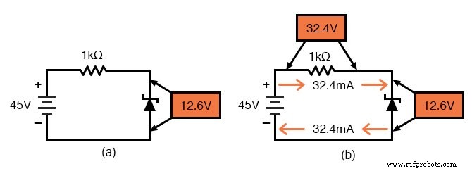
High‑Resistance Dropping Resistor
Using a higher series resistance, such as 100 kΩ, drastically reduces power dissipation (by 100×) but limits the load current that can be supplied. With the same 12.6 V Zener and 45 V supply, the current drops to 324 µA, yielding only 0.003 W in the Zener and 0.032 W in the resistor.
Illustration: 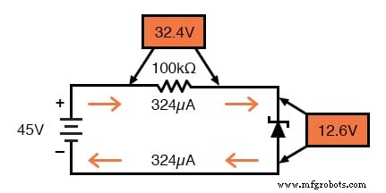
Impact of Load Resistance
Regulation is only effective when the load draws enough current to maintain the Zener’s breakdown voltage. If the load is too low, the series resistor drops too much voltage, leaving insufficient voltage across the Zener to trigger regulation.
Example with 500 Ω load and 1 kΩ resistor:
- Load current: 12.6 V / 500 Ω = 25.2 mA
- Series resistor current: 32.4 mA
- Zener current: 7.2 mA
Illustration: 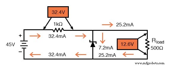
Contrast with 100 kΩ resistor and the same load:
Only 224 mV would appear across the load, far below the desired 12.6 V, because the series resistor cannot supply the required current.
Illustration: 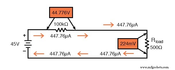
Analytical Approach Without the Zener
Removing the Zener simplifies the circuit to two resistors in series:
- Total resistance: 100 kΩ + 500 Ω ≈ 100.5 kΩ
- Current: 45 V / 100.5 kΩ ≈ 447.8 µA
- Voltage across load: 447.8 µA × 500 Ω ≈ 224 mV
Since this voltage is far below the Zener’s 12.6 V, the diode never reaches breakdown and cannot regulate the output.
Design Rule of Thumb
A Zener regulator works only if the load resistance is above a certain minimum value. If the load draws too much current, the series resistor will drop too much voltage, preventing the Zener from conducting. For a 100 kΩ series resistor and a 12.6 V Zener, the minimum load resistance is about 38.9 kΩ. Any load larger than this will allow the Zener to maintain the regulated voltage; loads smaller will result in a lower output.
Illustration: 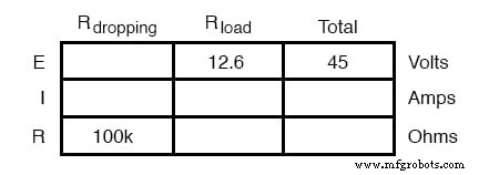
Why Use Zener Diodes?
Zener diodes offer a remarkably simple, inexpensive, and reliable method to generate a stable reference voltage. Although they dissipate power inefficiently compared to dedicated voltage regulators, their robustness and low component count make them ideal for low‑power or prototyping circuits. In high‑power designs, Zeners often serve as reference points for more efficient regulators.
Common Zener Diode Voltages
Below is a summary of standard Zener voltages for 0.5 W and 1.3 W devices. Datasheets typically list tolerances of ±5 % to ±10 % and a temperature coefficient of a few millivolts per degree Celsius.
| 0.5 W |
|---|
| 2.7 V, 3.0 V, 3.3 V, 3.6 V, 3.9 V, 4.3 V, 4.7 V, 5.1 V, 5.6 V, 6.2 V, 6.8 V, 7.5 V, 8.2 V, 9.1 V, 10 V, 11 V, 12 V, 13 V, 15 V, 16 V, 18 V, 20 V, 24 V, 27 V, 30 V |
| 1.3 W |
| 4.7 V, 5.1 V, 5.6 V, 6.2 V, 6.8 V, 7.5 V, 8.2 V, 9.1 V, 10 V, 11 V, 12 V, 13 V, 15 V, 16 V, 18 V, 20 V, 22 V, 24 V, 27 V, 30 V, 33 V, 36 V, 39 V, 43 V, 47 V, 51 V, 56 V, 62 V, 68 V, 75 V, 100 V, 200 V |
Zener Diode Clipper
A clipping circuit uses two back‑to‑back Zener diodes to limit the amplitude of a waveform symmetrically about zero. The series resistor controls the maximum current.
Illustration: 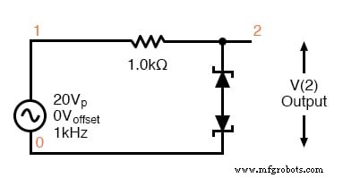
*SPICE 03445.eps D1 4 0 diode D2 4 2 diode R1 2 1 1.0k V1 1 0 SIN(0 20 1k) .model diode d bv=10 .tran 0.001m 2m .end
In this simulation, the Zeners are set to a 10 V breakdown. During the positive half‑cycle, the top Zener is reverse‑biased and conducts at 10 V, while the bottom Zener forward‑drops ~0.7 V, yielding an effective clipping level of 10.7 V. The negative half‑cycle clips symmetrically at –10.7 V.
Illustration: 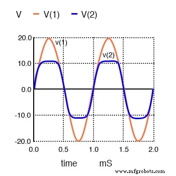
Key Takeaways
- Zener diodes are designed for reverse‑bias operation and provide a stable voltage once the breakdown threshold is reached.
- They function as voltage regulators by acting as a dynamic load that absorbs excess current, maintaining a constant output voltage.
- Proper design requires balancing series resistance, load resistance, and power ratings to ensure reliable operation.
Further Resources
Industrial Technology
- Voltage Regulator Experiment with a 12‑Volt Zener Diode
- Diodes: Fundamentals, Construction, and Applications
- Understanding Junction Diodes: From Crystal Detectors to Modern Silicon Devices
- Special-Purpose Diodes: Schottky, Tunnel, LED, Laser, Photodiode, and Solar Cell Innovations
- Exploring Advanced Diode Technologies: Varicaps, PINs, IMPATT, Gunn, and More
- Understanding Cobots: Collaborative Robots in Modern Industry
- Magnetic Labels: Versatile, Durable Inventory Solutions
- Understanding Metal Stickers: Durable, Secure Asset Identification Solutions
- Understanding Diode Forward Voltage: Key Concepts & Applications
- Voltage Relays Explained: Switching High Currents with Low Control Signals