


Diodes and Rectifiers: Fundamentals, Operation, and Key Parameters
All About Diodes
A diode is a semiconductor device that allows electric current to flow in one direction with low resistance, while blocking it in the opposite direction. In most modern circuit designs, the term "diode" refers to small‑signal devices rated up to 1 A. Devices that handle higher currents (above 1 A) are typically called rectifiers.
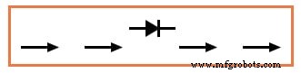
Semiconductor diodes are depicted in schematic diagrams with a distinctive symbol: a triangle pointing toward a line. The triangle represents the anode (P‑type side) and the line the cathode (N‑type side). See the illustration below for reference.
When inserted into a simple battery‑lamp circuit, the diode either permits or blocks current through the lamp, depending on the polarity of the applied voltage (illustrated below).
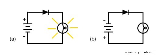
The diagram shows two scenarios: (a) forward‑biased, where current flows; (b) reverse‑biased, where current is blocked. A forward‑biased diode behaves like a closed switch, whereas a reverse‑biased diode behaves like an open switch.
By convention, the arrowhead in the diode symbol points in the direction of conventional current flow. If electron flow is considered, the current direction is opposite to the arrow.
Hydraulic Check Valve Analogy
Diode behavior can be compared to a hydraulic check valve, which permits fluid flow in only one direction. The figure below shows the valve in two states.
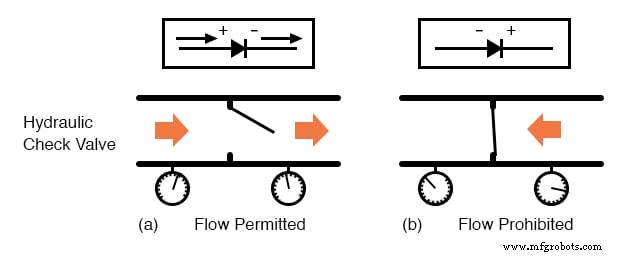
Check valves open when the fluid pressure on the downstream side exceeds that on the upstream side, and close otherwise. Similarly, a diode allows current to flow when the voltage polarity across it is correct, and blocks current when the polarity is reversed.
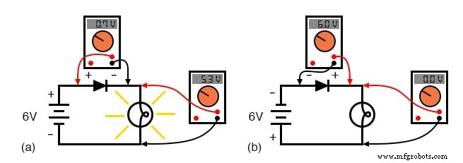
In a battery‑diode‑lamp circuit, the voltage drop across each component changes with biasing. The following diagram illustrates the voltage distribution.
Forward‑Bias Diode Configuration
When a diode is forward‑biased, it conducts and drops a small voltage—typically about 0.7 V for silicon diodes and 0.3 V for germanium diodes—while the majority of the source voltage appears across the load. In reverse bias, the diode blocks nearly all current and drops essentially the full supply voltage.
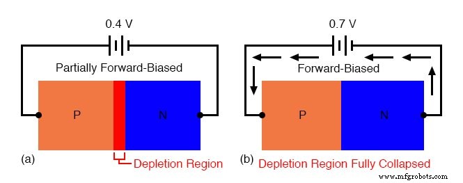
The forward voltage drop arises from the collapse of the depletion region at the P‑N junction under sufficient applied voltage. Without applied voltage, a thin depletion region exists, preventing conduction (see figure).
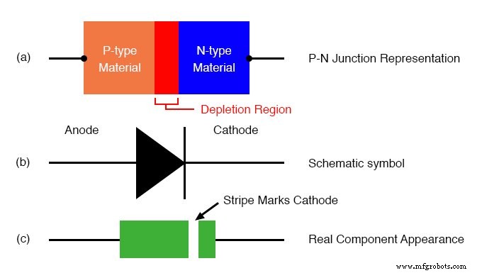
The schematic symbol (shown below) matches the physical part: the anode corresponds to the triangle tip (P‑type) and the cathode to the line (N‑type).
Reverse‑Bias Diode Configuration
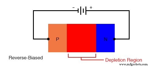
Applying a reverse voltage expands the depletion region, increasing resistance and effectively blocking current. The following image demonstrates the expanded region under reverse bias.
Forward Voltage
As the forward voltage increases, the depletion region thins until it collapses, enabling significant current flow. This threshold is known as the forward voltage. For silicon diodes, the typical forward voltage is 0.7 V; for germanium, it is 0.3 V. The value is largely determined by the junction’s material composition and remains relatively constant over a wide range of forward currents, which simplifies circuit analysis.
Diode Equation
The exact relationship between current and voltage in a diode is expressed by the Shockley diode equation:
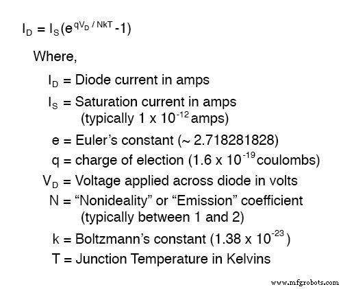
Here, kT/q is the thermal voltage (≈26 mV at room temperature). With a non‑ideality factor of 1, the equation simplifies to:
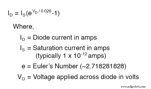
While most introductory analyses treat the forward voltage as a constant, understanding the exponential nature of the equation is essential for circuits that exploit this relationship—such as temperature sensors or precision rectifiers.
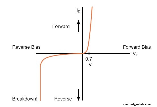
Reverse‑Biased Operation
In reverse bias, the diode blocks current, though a minute leakage current does flow—negligible for most applications. If the reverse voltage exceeds a diode’s specified limit, a destructive breakdown can occur. The maximum permissible reverse voltage is called the Peak Inverse Voltage (PIV), which varies with temperature: it increases as temperature rises and decreases as the device cools.
Typical rectifier diodes have a PIV of at least 50 V at room temperature, while specialized devices can reach several kilovolts.
Review
- A diode is a one‑way valve for electrical current.
- When the applied voltage permits current flow, the diode is forward‑biased.
- When the applied voltage blocks current, the diode is reverse‑biased.
- The voltage drop across a conducting diode is called the forward voltage; it varies only slightly with current and temperature.
- Silicon diodes exhibit a forward voltage of ~0.7 V.
- Germanium diodes exhibit a forward voltage of ~0.3 V.
- The maximum reverse voltage a diode can tolerate without breaking down is its Peak Inverse Voltage (PIV).
Related Worksheets
- Rectifying Diodes Worksheet
- PN Junctions Worksheet
Industrial Technology
- Diodes: Fundamentals, Construction, and Applications
- Understanding Junction Diodes: From Crystal Detectors to Modern Silicon Devices
- Exploring Advanced Diode Technologies: Varicaps, PINs, IMPATT, Gunn, and More
- Understanding the Shockley Diode: A Comprehensive Guide to PNPN Thyristors
- Understanding Voltage and Current: The Foundations of Electrical Flow
- Capacitors & Calculus: How Voltage Change Drives Current
- Inductors & Calculus: How Current Change Drives Voltage
- Series vs. Parallel Inductors: How Inductance Adds or Diminishes
- Protecting Solar Panels: How Blocking & Bypass Diodes Guard Against Shade and Faults
- Diodes Explained: Types, Functions, and Applications