


PWM Power Controller: Build a Pulse‑Width Modulated Lamp Driver
Parts and Materials
- Four 6‑volt batteries
- 100 µF electrolytic capacitor, 35 WVDC (e.g., Radio Shack #272‑1028)
- 0.1 µF non‑polarized capacitor (Radio Shack #272‑135)
- 555 timer IC (Radio Shack #276‑1723)
- Dual operational amplifier, 1458 (Radio Shack #276‑038)
- NPN power transistor (Radio Shack #276‑2041 or equivalent)
- Three 1N4001 rectifying diodes (Radio Shack #276‑1101)
- 10 kΩ linear potentiometer (Radio Shack #271‑1715)
- 33 kΩ resistor
- 12‑volt automotive tail‑light lamp
- Audio detector with headphones
Cross‑References
- Lessons In Electric Circuits, Vol. 3, Chap. 8: “Operational Amplifiers”
- Lessons In Electric Circuits, Vol. 2, Chap. 7: “Mixed‑Frequency AC Signals”
Learning Objectives
- Demonstrate the 555 timer as an astable multivibrator
- Use an op‑amp as a comparator
- Employ diodes to drop unwanted DC voltage
- Control power to a load via pulse‑width modulation (PWM)
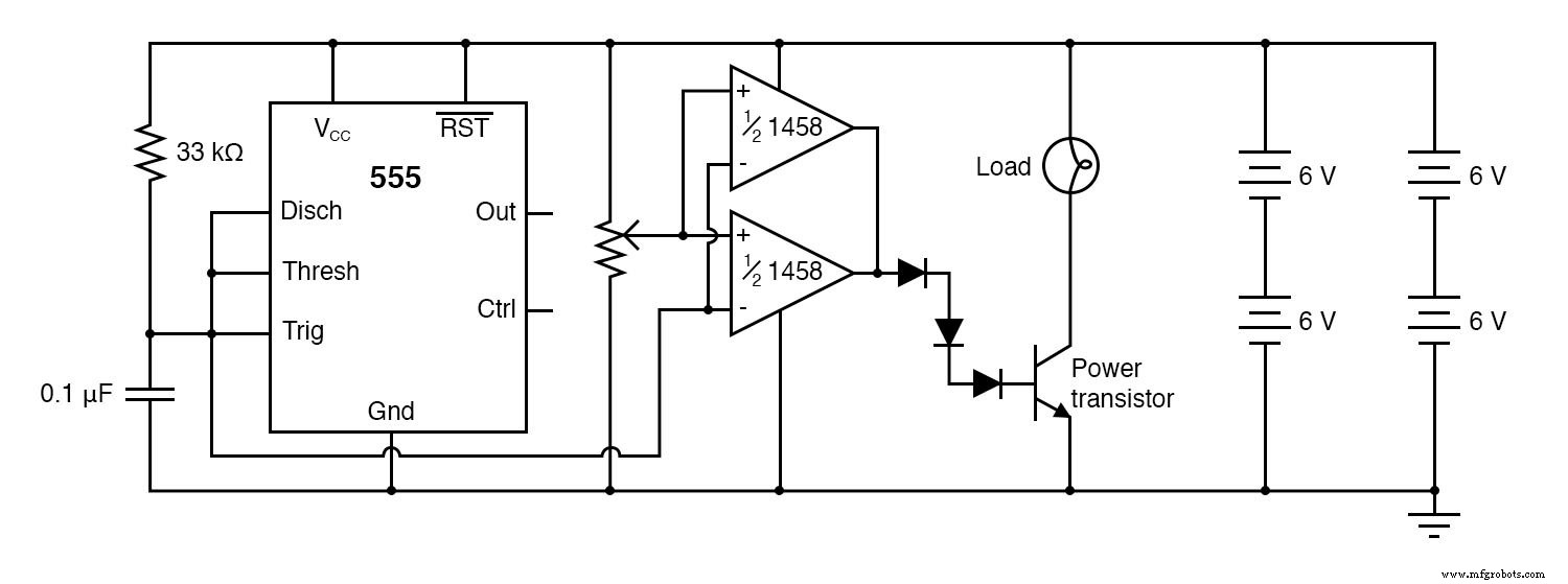
Schematic Diagram
Illustration
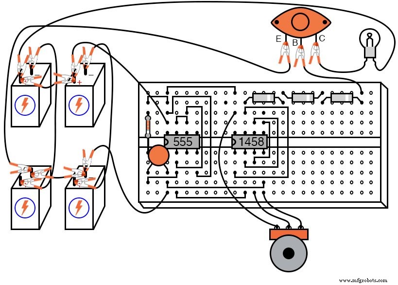
Instructions
This circuit uses a 555 timer to generate a sawtooth voltage across a capacitor. The capacitor voltage is compared with a reference voltage from a potentiometer by an op‑amp comparator. The comparator’s square‑wave output, whose duty cycle varies with the potentiometer, drives the base of a power transistor. The transistor switches the 12‑V lamp on and off rapidly, so the lamp’s average power is proportional to the duty cycle.
The PWM concept relies on the transistor’s low power dissipation when cut‑off (no current) and when saturated (minimal voltage drop). Compared with a rheostat, PWM achieves precise, energy‑efficient power control.
To observe the waveform relationships without a triple‑trace oscilloscope, replace the 0.1 µF capacitor with a 100 µF capacitor. This slows the 555’s frequency by roughly a factor of 1,000, allowing a DC voltmeter to track the capacitor rise and the op‑amp transition. The lamp will then visibly turn on and off at a slow rate; this demonstrates the underlying PWM mechanism.
Two identical op‑amps are wired in parallel to provide the necessary current into the transistor base. The 1458 series offers short‑circuit protection, preventing damage if one amp begins to drive high while the other drives low. Three silicon diodes in series drop ~2.1 V, ensuring the transistor fully turns off when the op‑amp output is low, since the 1458 cannot reach ground exactly.
Listening to the op‑amp output through headphones while adjusting the potentiometer reveals how duty cycle shapes the harmonic content. At 50 % duty cycle, the waveform is a perfect square wave with only odd harmonics, producing a distinct tonal quality. Deviating from 50 % introduces even harmonics, subtly altering the sound.
Related Worksheet
- Signal Modulation Worksheet
Industrial Technology
- Power Supply Circuits: Types, Design Principles, and Performance
- Pulse Width Modulation (PWM): Principles, Applications, and Design Insights
- Understanding Power in Electric Circuits: Measurement & Significance
- Three‑Phase Power Systems: Fundamentals and Benefits
- Accurate Power Measurement in AC Circuits: From Electrodynamometers to Hall‑Effect Sensors
- Implementing a PWM Controller in VHDL: Design, Simulation, and FPGA Demo
- Understanding Flicker: Impact on Power Quality and How Variable Speed Drives Help
- 555 Timer PWM DC Motor Speed Controller – Build & PCB Design Guide
- PWM Solar Charge Controllers: Function, Sizing, and Selection Guide
- Overvoltage Explained: Causes, Risks, and Prevention