


Implementing a PWM Controller in VHDL: Design, Simulation, and FPGA Demo
Pulse‑width modulation (PWM) turns a digital FPGA pin into a powerful analog controller. By switching the supply on and off at high speed, PWM delivers the exact average current a device needs, without ever generating a true analog voltage.
Typical PWM applications include audio output for speakers, dimming LEDs, and controlling the torque of induction motors such as servo motors, computer fans, pumps, and brushless DC motors for electric vehicles.
See also: RC servo controller using PWM from an FPGA pin
How PWM Works
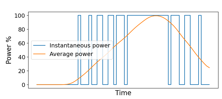
When a power supply is toggled between 100 % and 0 % at a high frequency, the time‑averaged current seen by the load is directly proportional to the fraction of time the supply is on. The following diagram illustrates the principle:
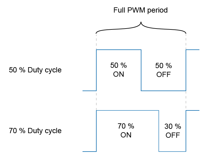
Duty Cycle
The duty cycle defines how long the PWM output stays high during each period. Expressed as a percentage, it is calculated from the binary counter value:
In a VHDL implementation we treat the duty cycle as an unsigned integer, giving us the full resolution of the PWM counter. A 0 % duty cycle turns the output permanently off, whereas a 100 % duty cycle keeps it continuously on. The achievable resolution is determined by the width of the counter.
To convert the binary duty‑cycle value to a percentage, use:
\mathit{duty\_cycle\_percentage} = \frac{\mathit{commanded\_duty\_cycle} * 100}{2^\mathit{pwm\_bits} - 1}
PWM Frequency
The PWM frequency is the inverse of the period:
\mathit{pwm\_freq} = \frac{1}{\mathit{pwm\_period}}
Choosing the right frequency depends on the target device. For LEDs, a few hundred hertz is sufficient to avoid visible flicker. Brushless DC motors, on the other hand, typically operate in the tens of kilohertz range; too low a frequency can produce mechanical vibrations, while too high a frequency wastes power.
Because the MOSFET switches are slower than the FPGA logic, operating the PWM too fast can cause the transistor to spend time in a partially conducting state, which dissipates extra heat.
PWM Generator Module
Below is a generic VHDL implementation of a PWM controller that can be instantiated with any counter width and clock division factor.
Entity Declaration
entity pwm is
  generic (
    pwm_bits : integer;
    clk_cnt_len : positive := 1
  );
  port (
    clk : in std_logic;
    rst : in std_logic;
    duty_cycle : in unsigned(pwm_bits - 1 downto 0);
    pwm_out : out std_logic
  );
end pwm;
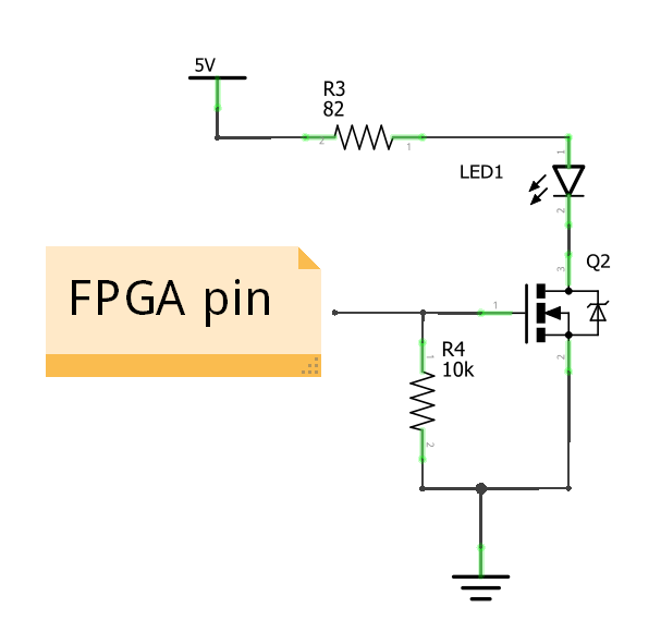
The clk and rst ports provide synchronous control. The duty_cycle input has a width defined by pwm_bits, so the counter resolution is directly configurable. The pwm_out signal is routed to the FPGA pin that drives the MOSFET gate.
Internal Signals
signal pwm_cnt : unsigned(pwm_bits - 1 downto 0);
signal clk_cnt : integer range 0 to clk_cnt_len - 1;
The pwm_cnt counter mirrors the duty‑cycle width. The clk_cnt counter implements an optional clock divider; setting clk_cnt_len to 1 disables the divider and removes the associated logic.
Clock‑Divider Process
CLK_CNT_PROC : process(clk)
begin
  if rising_edge(clk) then
    if rst = '1' then
      clk_cnt <= 0;
    else
      if clk_cnt < clk_cnt_len - 1 then
        clk_cnt <= clk_cnt + 1;
      else
        clk_cnt <= 0;
      end if;
    end if;
  end if;
end process;
With the default clk_cnt_len = 1, synthesis tools will eliminate this process automatically.
PWM Output Process
PWM_PROC : process(clk)
begin
  if rising_edge(clk) then
    if rst = '1' then
      pwm_cnt <= (others => '0');
      pwm_out <= '0';
    else
      if clk_cnt_len = 1 or clk_cnt = 0 then
        pwm_cnt <= pwm_cnt + 1;
        pwm_out <= '0';
        if pwm_cnt = unsigned(to_signed(-2, pwm_cnt'length)) then
          pwm_cnt <= (others => '0');
        end if;
        if pwm_cnt < duty_cycle then
          pwm_out <= '1';
        end if;
      end if;
    end if;
  end if;
end process;
The counter increments only when clk_cnt is zero, effectively throttling the PWM frequency. The conditional that resets pwm_cnt at its second‑highest value guarantees that a 100 % duty cycle is achievable.
\mathit{pwm\_hz} = \frac{\mathit{clk\_hz}}{(2^\mathit{pwm\_bits} - 1) * \mathit{clk\_cnt\_len}}
Top‑Level Design
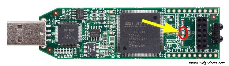
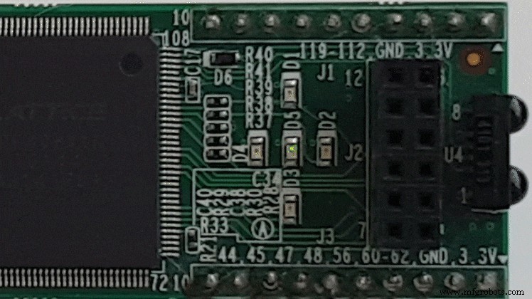
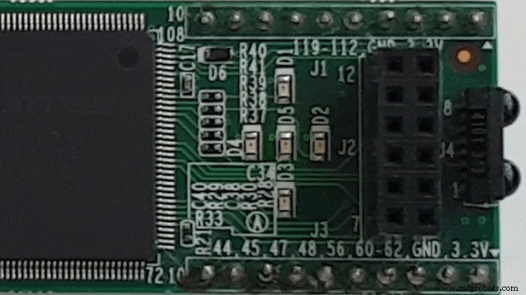
To demonstrate the PWM controller, the design drives the power‑on LED on a Lattice iCEstick FPGA. The board’s 12 MHz oscillator feeds a counter that drives the LED intensity in a sawtooth pattern.
Entity Declaration
entity pwm_led is
  generic (
    pwm_bits : integer := 8;
    cnt_bits : integer := 25;
    clk_cnt_len : positive := 47
  );
  port (
    clk : in std_logic;
    rst_n : in std_logic;
    led_1 : out std_logic;
    led_2 : out std_logic;
    led_3 : out std_logic;
    led_4 : out std_logic;
    led_5 : out std_logic
  );
end pwm_led;
The 12 MHz clock and the chosen generics produce a PWM frequency of approximately 1 kHz:
\frac{12e6}{(2^8 - 1) * 47} \approx 1 \text{ kHz}
The cnt_bits generic drives a 25‑bit sawtooth counter that controls the LED duty cycle. Its period is about 2.8 Hz:
\frac{2^{\mathit{cnt\_bits}}}{\mathit{clk\_hz}} = \frac{2^{25}}{12e6} \approx 2.8 \text{ Hz}
Only LED 5 is used; the other LEDs are tied low to avoid stray illumination.
Internal Signals and Wiring
architecture str of pwm_led is
  signal rst : std_logic;
  signal cnt : unsigned(cnt_bits - 1 downto 0);
  signal pwm_out : std_logic;
  alias duty_cycle is cnt(cnt'high downto cnt'length - pwm_bits);
begin
  led_1 <= '0';
  led_2 <= '0';
  led_3 <= '0';
  led_4 <= '0';
  led_5 <= pwm_out;
The rst signal is a synchronised, non‑inverted version of the external reset. The alias duty_cycle maps the most significant bits of cnt to the PWM controller.
Module Instantiations
RESET : entity work.reset(rtl)
  port map (
    clk => clk,
    rst_n => rst_n,
    rst => rst
  );

PWM : entity work.pwm(rtl)
  generic map (
    pwm_bits => pwm_bits,
    clk_cnt_len => clk_cnt_len
  )
  port map (
    clk => clk,
    rst => rst,
    duty_cycle => duty_cycle,
    pwm_out => pwm_out
  );

COUNTER : entity work.counter(rtl)
  generic map (
    counter_bits => cnt'length
  )
  port map (
    clk => clk,
    rst => rst,
    count_enable => '1',
    counter => cnt
  );
Simulation
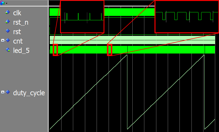
Generics make it easy to speed up simulation. By reducing cnt_bits and clk_cnt_len we can observe full PWM cycles in a few microseconds instead of several seconds.
Testbench instantiation:
DUT : entity work.pwm_led(str)
  generic map (
    pwm_bits => 8,
    cnt_bits => 16,
    clk_cnt_len => 1
  );
The waveform in ModelSim shows a sawtooth counter driving the LED brightness. A brief “on” pulse appears at the tip of each cycle when the duty cycle reaches its maximum value.
FPGA Implementation
After synthesis with iCEcube2, the design consumes only 5 % of the 64 available LUTs on the ice40hx1ktq144 part:
Resource Usage Report for pwm_led

Mapping to part: ice40hx1ktq144
Cell usage:
GND             3 uses
SB_CARRY        31 uses
SB_DFF          5 uses
SB_DFFSR        39 uses
SB_GB           1 use
VCC             3 uses
SB_LUT4         64 uses

I/O ports: 7
I/O primitives: 7
SB_GB_IO       1 use
SB_IO          6 uses

I/O Register bits:                  0
Register bits not including I/Os:   44 (3%)
Total load per clock:
   pwm_led|clk: 1

@S |Mapping Summary:
Total  LUTs: 64 (5%)
Programming the FPGA over USB with the Diamond standalone programmer was straightforward. The resulting LED animation shows a smooth brightness ramp followed by a brief darkening before the cycle repeats.
Breathing LED with a Sine‑Wave Duty Cycle
Replacing the sawtooth counter with a sine‑wave lookup table produces a natural “breathing” effect, commonly seen on notification LEDs.
In a forthcoming article, we’ll show how to build a sine‑wave generator using block RAM and integrate it into the pwm_led design.
Read the next post: How to create a breathing LED effect using a sine wave stored in block RAM
See also: RC servo controller using PWM from an FPGA pin
VHDL
- PWM Power Controller: Build a Pulse‑Width Modulated Lamp Driver
- Creating String Lists in VHDL: Best Practices & Example
- Designing a Robust VHDL Ring Buffer FIFO in Block RAM
- Implementing a Dynamic Linked List in VHDL with Protected Types and Access Pointers
- Designing a Finite‑State Machine in VHDL: A Practical Traffic Light Example
- Build a Reliable Timer in VHDL: Counting Clock Cycles to Hours
- Building a Clock‑Triggered Process in VHDL: A Practical Guide
- Mastering Concurrent Statements in VHDL: A Practical Guide
- Mastering std_logic_vector: Creating Signal Vectors in VHDL
- Using Sensitivity Lists in VHDL Processes for Reliable RTL Design