


Building a Clock‑Triggered Process in VHDL: A Practical Guide
The majority of VHDL designs employ clocked logic—commonly referred to as synchronous or sequential logic. A clocked process activates solely on the master clock’s edge, regardless of changes in other input signals.
The fundamental element of clocked logic is the flip‑flop. In this tutorial we focus on the positive‑edge‑triggered flip‑flop with a negative reset. See the schematic below:

As a sample‑and‑hold device, the flip‑flop captures the input value on the rising clock edge and retains that value until the next rising edge or until the reset signal is asserted.
Note: This post is part of the Basic VHDL Tutorials series.
All clocked processes trigger in unison and sample their inputs simultaneously. The clock establishes discrete time steps, allowing designers to partition complex logic into clear, cycle‑by‑cycle events.
Flip‑flops, or arrays thereof, are also called registers.
The sensitivity list of a clocked process typically contains only the clock signal, because the process awakens exclusively on a clock flank. Additional inputs are ignored for triggering purposes.
Below is a reusable template for a clocked process with a synchronous reset:
process(Clk) is
begin
    if rising_edge(Clk) then
        if nRst = '0' then
            <reset all output signals here>
        else
            <main logic here>
        end if;
    end if;
end process;
Exercise
In the accompanying video tutorial we walk through the creation of a clocked process in VHDL.
Testbench Code
The final testbench for the flip‑flop:
library ieee;
use ieee.std_logic_1164.all;
use ieee.numeric_std.all;

entity T17_ClockedProcessTb is
end entity;

architecture sim of T17_ClockedProcessTb is

    constant ClockFrequency : integer := 100e6; -- 100 MHz
    constant ClockPeriod    : time    := 1000 ms / ClockFrequency;

    signal Clk    : std_logic := '1';
    signal nRst   : std_logic := '0';
    signal Input  : std_logic := '0';
    signal Output : std_logic;

begin

    -- The Device Under Test (DUT)
    i_FlipFlop : entity work.T17_FlipFlop(rtl)
    port map(
        Clk    => Clk,
        nRst   => nRst,
        Input  => Input,
        Output => Output);

    -- Clock generation
    Clk <= not Clk after ClockPeriod / 2;

    -- Testbench sequence
    process is
    begin
        -- Release the DUT from reset
        nRst <= '1';

        wait for 20 ns;
        Input <= '1';
        wait for 22 ns;
        Input <= '0';
        wait for 6 ns;
        Input <= '1';
        wait for 20 ns;

        -- Apply reset
        nRst <= '0';

        wait;
    end process;

end architecture;
Flip‑Flop Module
Implementation of the positive‑edge flip‑flop with a negative reset:
library ieee;
use ieee.std_logic_1164.all;
use ieee.numeric_std.all;

entity T17_FlipFlop is
port(
    Clk    : in std_logic;
    nRst   : in std_logic; -- Negative reset
    Input  : in std_logic;
    Output : out std_logic);
end entity;

architecture rtl of T17_FlipFlop is
begin

    -- Flip‑flop with synchronized reset
    process(Clk) is
    begin

        if rising_edge(Clk) then
            if nRst = '0' then
                Output <= '0';
            else
                Output <= Input;
            end if;
        end if;

    end process;

end architecture;
Waveform Observation
After running the simulation in ModelSim and zooming into the timeline, the waveform clearly shows the output updating only on rising clock edges:
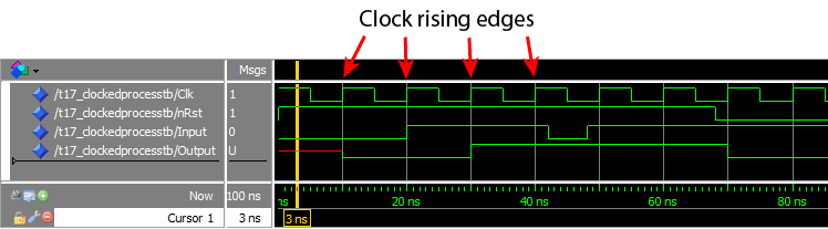
Analysis
The output changes exclusively at rising clock edges. Any input transition that occurs between two rising edges—such as the negative dip starting at ~45 ns—is not captured, because the flip‑flop samples only at the edge.
Below is an animation that visualizes the relationship between the input, clock, and output:
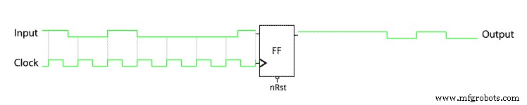
Key observations:
- The one‑clock‑period input pulse at 20 ns is synchronous to the clock and produces a delayed response in the output.
- During simulation, events occur in zero‑time steps (delta cycles). Because the flip‑flop reads the input and updates the output in the same delta cycle, it captures the pre‑edge input value.
In practice, a flip‑flop requires a stable input for a brief period before and after the clock edge—known as setup and hold times. These constraints are automatically handled by synthesis tools when converting VHDL to a netlist.
For a deeper dive into simulation time steps, see Delta cycles explained.
Takeaway
- Clocked processes with synchronous reset include only the clock in the sensitivity list.
- Using
if rising_edge(Clk)guarantees activation strictly on the clock’s rising edge. - In a synchronous design, all state changes occur at the active clock edge.
Ready to test your knowledge? Take the Basic VHDL Quiz – part 3 or continue to the next tutorial.
VHDL
- Creating String Lists in VHDL: Best Practices & Example
- Implementing a PWM Controller in VHDL: Design, Simulation, and FPGA Demo
- Implementing a Dynamic Linked List in VHDL with Protected Types and Access Pointers
- Leveraging In‑Process Procedures for Cleaner VHDL FSM Design
- Designing a Finite‑State Machine in VHDL: A Practical Traffic Light Example
- Build a Reliable Timer in VHDL: Counting Clock Cycles to Hours
- Mastering Concurrent Statements in VHDL: A Practical Guide
- Mastering std_logic_vector: Creating Signal Vectors in VHDL
- Using Sensitivity Lists in VHDL Processes for Reliable RTL Design
- Your First VHDL Program: A Step‑by‑Step Hello World Tutorial