


Designing a Finite‑State Machine in VHDL: A Practical Traffic Light Example
A finite‑state machine (FSM) is a deterministic logic model whose output depends not only on the current input but also on the sequence of past inputs and outputs. In FPGA design and time‑dependent VHDL algorithms, an FSM is the go‑to abstraction for capturing stateful behaviour.
FSMs in VHDL are typically implemented as clocked processes that use a state signal to remember the last configuration. The state signal acts as an internal register, allowing the design to react to events that span multiple clock cycles.
Basic VHDL Tutorials – Part 3
Traffic Lights as an FSM
Consider a four‑way intersection controlled by traffic lights. The lights cycle through a finite set of visible states – for example, North/South red, North/South green, West/East red, etc. The timing of each state (5 s for red or yellow, 60 s for green) is driven by elapsed clock cycles.
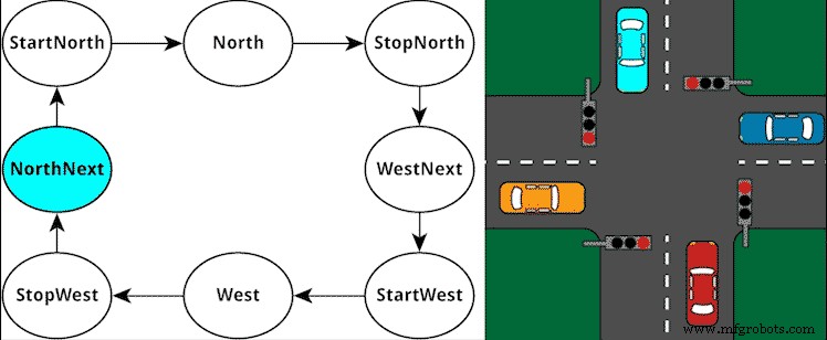
We model these behaviours by defining an enumerated type that lists all possible states:
type t_State is (NorthNext, StartNorth, North, StopNorth,
                 WestNext, StartWest, West, StopWest);
Then we declare a signal of that type to hold the current state:
signal State : t_State;
With the state signal in place, the FSM logic lives inside a single clocked process that uses a case statement. Each when branch corresponds to a distinct state and contains the output assignments for that state. A counter tracks the elapsed time and drives the transition to the next state when its value reaches a predefined threshold.
One‑Process FSM Template
process(Clk) is
begin
    if rising_edge(Clk) then
        if nRst = '0' then
            State   <= <reset_state>;
            Counter <= 0;
        else
            case State is
                when <state_name> =>
                    <set_outputs_for_this_state_here>
                    if <state_change_condition_is_true> then
                        State <= <next_state_name>;
                    end if;
                ...
            end case;
        end if;
    end if;
end process;
Note: You can implement FSMs using one‑, two‑, or three‑process styles. See FSM Styles Explained.
Practical Exercise
Below is a complete, synthesizable example that implements a traffic‑light controller. The design uses a 100 Hz clock to simplify simulation while still demonstrating realistic timing.
Testbench
library ieee;
use ieee.std_logic_1164.all;
use ieee.numeric_std.all;

entity T20_FiniteStateMachineTb is
end entity;

architecture sim of T20_FiniteStateMachineTb is
    constant ClockFrequencyHz : integer := 100; -- 100 Hz
    constant ClockPeriod : time := 1000 ms / ClockFrequencyHz;

    signal Clk         : std_logic := '1';
    signal nRst        : std_logic := '0';
    signal NorthRed    : std_logic;
    signal NorthYellow : std_logic;
    signal NorthGreen  : std_logic;
    signal WestRed     : std_logic;
    signal WestYellow  : std_logic;
    signal WestGreen   : std_logic;
begin
    i_TrafficLights : entity work.T20_TrafficLights(rtl)
        generic map(ClockFrequencyHz => ClockFrequencyHz)
        port map(
            Clk         => Clk,
            nRst        => nRst,
            NorthRed    => NorthRed,
            NorthYellow => NorthYellow,
            NorthGreen  => NorthGreen,
            WestRed     => WestRed,
            WestYellow  => WestYellow,
            WestGreen   => WestGreen);

    Clk <= not Clk after ClockPeriod / 2;

    process is
    begin
        wait until rising_edge(Clk);
        wait until rising_edge(Clk);
        nRst <= '1';
        wait;
    end process;
end architecture;
State‑Machine Module
library ieee;
use ieee.std_logic_1164.all;
use ieee.numeric_std.all;

entity T20_TrafficLights is
    generic(ClockFrequencyHz : integer);
    port(
        Clk         : in std_logic;
        nRst        : in std_logic; -- Active low reset
        NorthRed    : out std_logic;
        NorthYellow : out std_logic;
        NorthGreen  : out std_logic;
        WestRed     : out std_logic;
        WestYellow  : out std_logic;
        WestGreen   : out std_logic);
end entity;

architecture rtl of T20_TrafficLights is
    type t_State is (NorthNext, StartNorth, North, StopNorth,
                     WestNext, StartWest, West, StopWest);
    signal State : t_State;
    signal Counter : integer range 0 to ClockFrequencyHz * 60;
begin
    process(Clk) is
    begin
        if rising_edge(Clk) then
            if nRst = '0' then
                State   <= NorthNext;
                Counter <= 0;
                NorthRed    <= '1';
                NorthYellow <= '0';
                NorthGreen  <= '0';
                WestRed     <= '1';
                WestYellow  <= '0';
                WestGreen   <= '0';
            else
                -- Default outputs
                NorthRed    <= '0';
                NorthYellow <= '0';
                NorthGreen  <= '0';
                WestRed     <= '0';
                WestYellow  <= '0';
                WestGreen   <= '0';
                Counter <= Counter + 1;

                case State is
                    when NorthNext =>
                        NorthRed <= '1';
                        WestRed  <= '1';
                        if Counter = ClockFrequencyHz * 5 - 1 then
                            Counter <= 0;
                            State   <= StartNorth;
                        end if;
                    when StartNorth =>
                        NorthRed    <= '1';
                        NorthYellow <= '1';
                        WestRed     <= '1';
                        if Counter = ClockFrequencyHz * 5 - 1 then
                            Counter <= 0;
                            State   <= North;
                        end if;
                    when North =>
                        NorthGreen <= '1';
                        WestRed    <= '1';
                        if Counter = ClockFrequencyHz * 60 - 1 then
                            Counter <= 0;
                            State   <= StopNorth;
                        end if;
                    when StopNorth =>
                        NorthYellow <= '1';
                        WestRed     <= '1';
                        if Counter = ClockFrequencyHz * 5 - 1 then
                            Counter <= 0;
                            State   <= WestNext;
                        end if;
                    when WestNext =>
                        NorthRed <= '1';
                        WestRed  <= '1';
                        if Counter = ClockFrequencyHz * 5 - 1 then
                            Counter <= 0;
                            State   <= StartWest;
                        end if;
                    when StartWest =>
                        NorthRed   <= '1';
                        WestRed    <= '1';
                        WestYellow <= '1';
                        if Counter = ClockFrequencyHz * 5 - 1 then
                            Counter <= 0;
                            State   <= West;
                        end if;
                    when West =>
                        NorthRed  <= '1';
                        WestGreen <= '1';
                        if Counter = ClockFrequencyHz * 60 - 1 then
                            Counter <= 0;
                            State   <= StopWest;
                        end if;
                    when StopWest =>
                        NorthRed   <= '1';
                        WestYellow <= '1';
                        if Counter = ClockFrequencyHz * 5 - 1 then
                            Counter <= 0;
                            State   <= NorthNext;
                        end if;
                end case;
            end if;
        end if;
    end process;
end architecture;
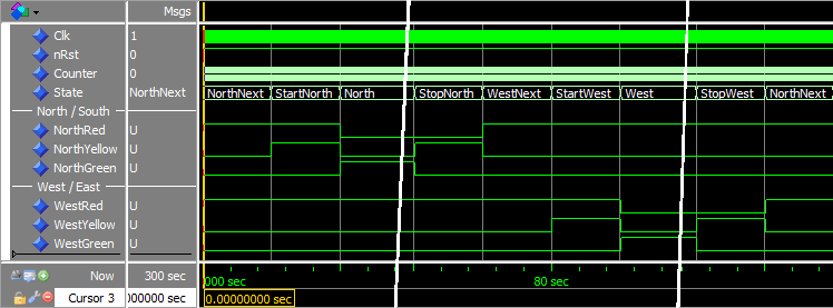
Running the simulation for five minutes produces a waveform that shows the FSM cycling through its eight states, with green phases lasting one minute each.
Analysis
Key takeaways from the code:
- Enumerated types restrict the
Statesignal to a known set of valid values, improving safety and readability. - All outputs are driven with a default value at the start of the process; subsequent state branches override only the signals that change.
- The
Countervariable is the timing engine, and its threshold values (5 s, 60 s) are derived from the clock frequency.
The resulting waveform confirms that the FSM advances correctly: the State signal toggles through the eight defined states, and each green phase persists for one minute.
Takeaway
- Finite‑state machines are the standard way to implement sequential logic in VHDL.
- A
casestatement inside a clocked process cleanly maps each state to its behaviour. - Enumerated types give compile‑time safety by limiting the set of permissible state values.
Proceed to the next tutorial for advanced FSM techniques.
VHDL
- Maximizing Performance of Qt State Machines
- Creating String Lists in VHDL: Best Practices & Example
- Implementing a PWM Controller in VHDL: Design, Simulation, and FPGA Demo
- Designing a Robust VHDL Ring Buffer FIFO in Block RAM
- Implementing a Dynamic Linked List in VHDL with Protected Types and Access Pointers
- Build a Reliable Timer in VHDL: Counting Clock Cycles to Hours
- Building a Clock‑Triggered Process in VHDL: A Practical Guide
- Mastering Concurrent Statements in VHDL: A Practical Guide
- Mastering std_logic_vector: Creating Signal Vectors in VHDL
- Using Sensitivity Lists in VHDL Processes for Reliable RTL Design