


Pulse Width Modulation (PWM): Principles, Applications, and Design Insights
Pulse Width Modulation (PWM) employs precise digital waveforms to regulate power delivery, offering a low‑hardware path to analog signals.
In linear power supplies, heat is a major drawback because variable resistors must carry substantial current continuously. Digital switching devices, on the other hand, dissipate most of their power only during the brief transition between on and off states. This follows the fundamental power equation:
P = V × I – when either voltage or current is near zero, power consumption is minimal. PWM exploits this by keeping the transistor fully on or off for most of the cycle, thus reducing average power and heat.
Because the PWM waveform can be freely modulated without the need for continuous data capture (except in high‑end controllers), it behaves much like an analog control system while retaining digital simplicity.
Duty Cycle
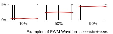
The duty cycle defines the proportion of time the signal stays high within one period. While a 50% duty cycle is the conventional “balanced” case, PWM allows any value from 0% (completely off) to 100% (fully on). The following illustration shows 10%, 50%, and 90% duty cycles at the same frequency, though the frequency can vary independently.
Loads such as resistors naturally integrate the average power proportional to the duty cycle. LEDs, which exhibit nonlinear current‑to‑light relationships, respond linearly to PWM, enabling precise brightness control. Motors also benefit from the responsiveness of PWM for speed regulation.
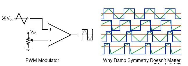
One common method to generate PWM is by comparing a sawtooth (or triangle) waveform with a reference level. The linearity of the ramp and its frequency—acting as the sampling rate—are critical for accurate duty‑cycle control.
When no computation is required, PWM can operate at very high speeds limited mainly by the comparator’s bandwidth. Many microcontrollers feature dedicated PWM modules capable of on‑the‑fly signal generation.
Applications
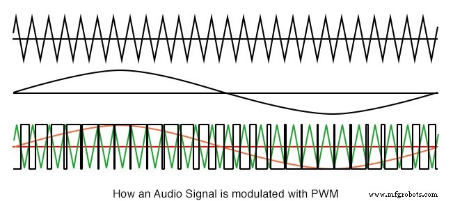
Pulse Width Modulation is integral to Class D audio amplifiers. By raising the output voltage and choosing a switching frequency beyond the human hearing range (typically 44 kHz), the amplifier reproduces the audio waveform while the loudspeaker only responds to the low‑frequency content. Higher switching rates (e.g., 100 kHz) further improve fidelity.
Motor speed control is another dominant use case. PWM allows efficient regulation of high‑current motors, especially at low revolutions per minute (RPM), where linear voltage scaling would waste power.
H‑Bridges
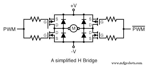
When paired with an H‑bridge configuration, PWM can effectively double the voltage across a load by switching the supply between both sides of the load. For inductive loads such as motors, flyback diodes suppress voltage spikes that could damage the transistors. The inherent inductance also filters out high‑frequency PWM components.
However, careful gate‑drive sequencing is essential to avoid “shoot‑through,” where both upper and lower transistors conduct simultaneously, potentially overloading the supply. Dedicated driver ICs provide the necessary dead‑time to prevent this condition.
Switching‑Mode Power Supplies (SMPS)
SMPS designs frequently use PWM, though other modulation schemes exist. By storing energy in inductors and capacitors during the off‑cycle, these supplies can achieve efficiencies exceeding 90% in optimal topologies.
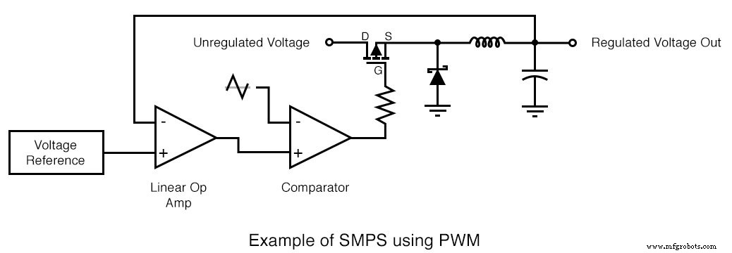
For example, a 90% efficient SMPS converting 12 VDC to 5 VDC at 10 A would draw about 4.6 A from the input (12 V × 4.6 A ≈ 55 W). The remaining 5 W manifests as minimal heat, keeping the regulator cooler than its linear counterpart, albeit with slightly higher noise.
RELATED WORKSHEETS:
- Design Project: Pulse‑Width Modulation (PWM) Signal Generator Worksheet
- Signal Modulation Worksheet
Industrial Technology
- Understanding AC Circuits: A Beginner's Guide
- PWM Power Controller: Build a Pulse‑Width Modulated Lamp Driver
- Power Sources: AC and DC Explained
- Protective Relays: Safeguarding Industrial Power Systems
- Amplifiers: Harnessing Active Devices to Boost Power
- Understanding Bels and Decibels: From Power Gain to Voltage Conversion
- Rectifier Circuits: From Half‑Wave to Polyphase Full‑Wave Designs
- Implementing a PWM Controller in VHDL: Design, Simulation, and FPGA Demo
- Designing a Reliable PWM Circuit for Precise DC Motor Speed Control
- IC 555 PWM Generator: Mastering Pulse Width Modulation for Precise Power Control