


Linear Ramp Generator with the 555 Timer – A Practical Lab Guide
Parts and Materials
- Two 6 V batteries (or a 12 V supply)
- 470 µF electrolytic capacitor, 35 V rating (Radio Shack #272‑1030 or equivalent)
- 0.1 µF non‑polarized capacitor (Radio Shack #272‑135)
- 555 timer IC (Radio Shack #276‑1723)
- Two PNP transistors (2N2907 or 2N3906 recommended; Radio Shack #276‑1604 is a 15‑pack that works well)
- Two LEDs (Radio Shack #276‑026 or equivalent)
- 100 kΩ resistor
- 47 kΩ resistor
- Two 510 Ω resistors
- Audio detector with headphones
The 470 µF capacitor’s voltage rating only needs to comfortably exceed the supply voltage—12 V in this example. Be sure to observe polarity when installing it.
Cross‑References
- Lessons In Electric Circuits, Vol. 1, Ch. 13: "Capacitors"
- Lessons In Electric Circuits, Vol. 4, Ch. 10: "Multivibrators"
Learning Objectives
- Demonstrate the 555 timer as an astable multivibrator.
- Show a practical application of a current‑mirror circuit.
- Illustrate the relationship between capacitor current and voltage rate‑of‑change.
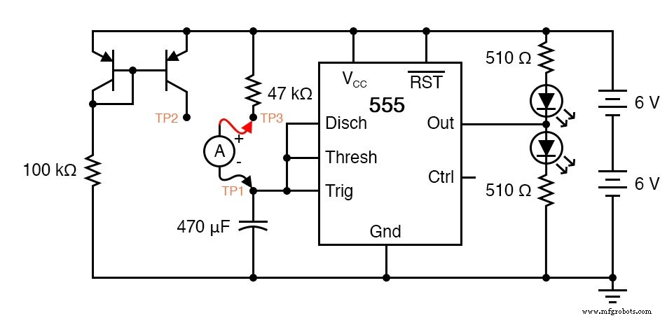
Schematic Diagram
Illustration
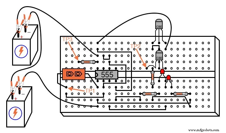
Procedure
We use the 555 timer in astable mode to generate an oscillator that drives a capacitor. The experiment compares two charging paths: a classic RC network and a constant‑current source implemented with a current‑mirror made from two PNP transistors.
Connect test point TP1 to TP3 with a jumper. The 470 µF capacitor now charges through the 47 kΩ resistor. When its voltage reaches two‑thirds of the supply, the 555 switches to discharge, pulling the voltage down to one‑third of the supply almost instantaneously. This cycle repeats, producing a sawtooth waveform.
Measure the capacitor voltage with a digital multimeter. The curve will rise steeply at first and then level off as it approaches 2/3 Vcc, characteristic of an RC charge curve.
Next, remove the jumper from TP3 and attach it to TP2. The capacitor now receives a controlled current from the current‑mirror formed by the two PNP transistors. Measure the voltage again. The charging curve should now be linear—a true ramp—because the current remains essentially constant, satisfying i = C·dV/dt.
To verify the current behavior, replace the jumper with an ammeter set to the microamp range. When connected between TP1 and TP3, the current will start high and taper off. When connected between TP1 and TP2, the current should be far more stable, with minimal AC component.
For a practical touch, try warming one of the transistors. Heating the controlling transistor (connected to the 100 kΩ resistor) decreases the mirrored current, while heating the controlled transistor increases it. In a precision setup, the two transistors are physically bonded to keep their temperatures matched.
The circuit also functions at audio frequencies. Replace the 470 µF capacitor with a 0.1 µF one and feed the 555 output to the audio detector. The detector will produce a clear tone. While a DC multimeter cannot resolve the rapid voltage swings, you can still use the ammeter to compare AC and DC currents in both RC and constant‑current modes.
If the current mirror were perfect, the AC component of the measured current would be zero, indicating a perfectly constant charging current.
Industrial Technology
- Hands‑On Guide to Current Dividers: Build, Measure, and Simulate with a 6 V Battery
- 555 Timer Astable Oscillator: LED Demo & Duty Cycle Exploration
- The 555 Integrated Circuit: A Timeless Benchmark in Analog Design
- CMOS 555 LED Flasher – Long‑Duration, Low‑Power Red LED Pulsing Circuit
- Capacitor Types: Polarized, Non-Polarized, and Variable Explained
- Peak Detector: How It Works and Practical Applications
- Common-Emitter Amplifier Limitations: Distortion, Temperature, and High‑Frequency Challenges
- AC Capacitor Circuits: Capacitive Reactance, Phase Shift, and Power Behavior
- Electric Pendulum: How Capacitors and Inductors Exchange Energy
- Preventing High Inrush Currents in Capacitor Switching: Proven Strategies for Reliable Power Systems