


Using a Musical Keyboard as a Variable‑Frequency AC Signal Generator
Materials Needed
- Electronic musical keyboard (ideally with a range of voices such as piano, flute, harp)
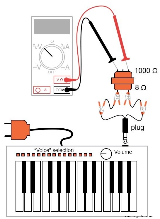
- Mono (single‑channel) headphone jack adapter
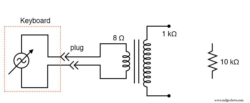
- Impedance‑matching transformer (1 kΩ to 8 Ω, e.g., Radio Shack #273‑1380)
- 10 kΩ resistor
This experiment demonstrates how a standard musical keyboard can act as a low‑cost, variable‑frequency AC voltage source. The keyboard’s headphone output supplies the AC waveform, which can be amplified or stepped up using a transformer for further measurements.
Most keyboards have at least a few dozen instrument voices; the panflute or flute tones typically generate the cleanest sine‑wave output, making them ideal for initial trials.
The mono plug should match the keyboard’s headphone jack. When connected, the keyboard’s built‑in speaker is disconnected, and the AC signal appears at the plug’s wires.
Use an audio output transformer (8 Ω secondary) to step up the voltage; if a power transformer is used instead, connect the keyboard to the low‑voltage winding for a step‑up effect. Because keyboard outputs are low voltage, there is no shock risk.
Key Concepts
- Amplitude vs. Frequency: Understand how voltage level and waveform frequency are independent.
- AC Measurement: Use a multimeter with voltage and frequency functions to record waveform characteristics.
- Transformer Operation: Observe step‑up ratios and how impedance matching affects signal quality.
Cross‑References
- Lessons In Electric Circuits, Vol. 2, Chap. 1 – “Basic AC Theory”
- Lessons In Electric Circuits, Vol. 2, Chap. 7 – “Mixed‑Frequency AC Signals”
Schematic Diagram
Illustration
Procedure
1. Set the keyboard to a sustained‑note mode so the amplitude remains constant while a key is held down.
2. Connect the mono plug to the keyboard’s headphone jack and to your measurement circuit.
3. Use a multimeter to read the raw AC voltage at the plug. Then, measure the stepped‑up voltage across the transformer’s secondary. Note the ratio between the two readings.
4. If your meter offers a frequency display, record the frequency for each note you play. You should observe the standard equal‑tempered scale: each octave doubles the frequency, and each semitone increases the frequency by a factor of 2^(1/12).
5. Verify that changing the keyboard’s volume (amplitude) does not affect the measured frequency.
6. Attach a 10 kΩ resistor in series with the headphone output and measure the AC current. The current’s frequency should match that of the voltage for each note.
Worksheet
- Mixed‑Frequency Signals Worksheet
Industrial Technology
- Transformer‑Based Power Supply: Building a Safe 12 VAC Step‑Down Circuit
- Construct a Basic Transformer: Step‑by‑Step Guide
- Signal Coupling: Understanding AC Noise in Telephone Cables
- Current Signal Systems: The 4‑20 mA Loop Explained
- Transformers with Multiple Windings: From Taps to Variacs – A Comprehensive Guide
- Three-Phase Transformer Circuits: Design, Wiring, and Practical Applications
- RF Transformers: Design, Function, and Key Applications
- Ensuring Signal Integrity in High-Speed PCB Design
- Understanding the Scott‑T Transformer: Converting Between Two‑Phase and Three‑Phase Power
- Mastering Bluetooth Signal Generators: Complete Guide & DIY Tips