


Signal Coupling: Understanding AC Noise in Telephone Cables
PARTS AND MATERIALS
- 6 V battery
- 0.22 µF capacitor (Radio Shack catalog #272‑1070 or equivalent)
- 0.047 µF capacitor (Radio Shack catalog #272‑134 or equivalent)
- Small hobby motor, permanent‑magnet type (Radio Shack catalog #273‑223 or equivalent)
- Audio detector with headphones
- Several feet of telephone cable (Radio Shack catalog #278‑872) – any unshielded multiconductor cable will work; thinner conductors (≈24‑AWG) amplify the effect.
Telephone cable is widely available at hardware stores. Using any unshielded multiconductor cable is fine, but the finer the conductors, the more pronounced the observed coupling.
CROSS‑REFERENCES
- Lessons In Electric Circuits, Volume 2, chapter 7: “Mixed‑Frequency AC Signals”
- Lessons In Electric Circuits, Volume 2, chapter 8: “Filters”
LEARNING OBJECTIVES
- Demonstrate how AC signals can be coupled while DC is blocked from a measurement device.
- Show how stray coupling arises in cables.
- Identify practical techniques to reduce inter‑cable coupling.
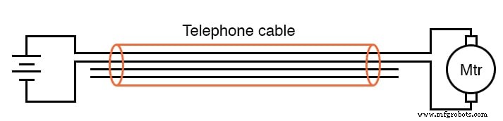
SCHEMATIC DIAGRAM
ILLUSTRATION
INSTRUCTIONS
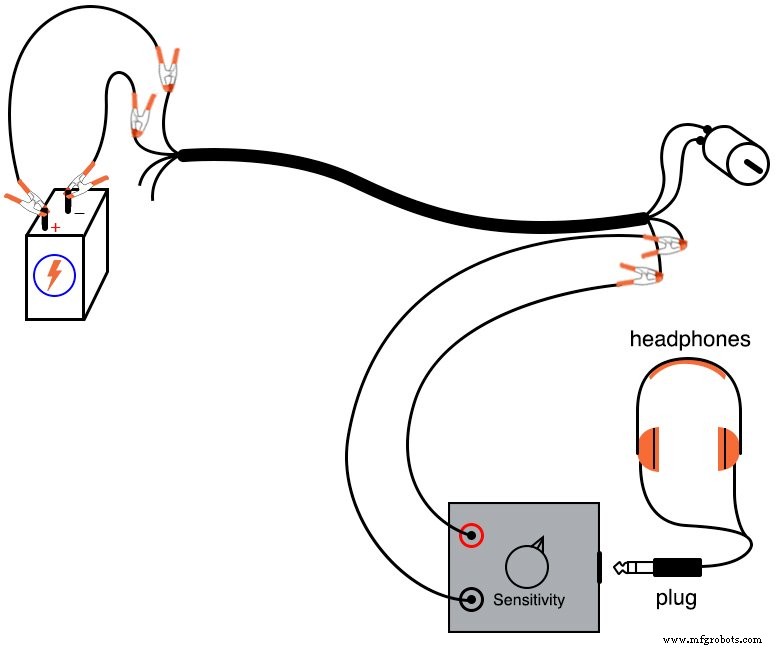
1. Connect the motor to the battery using two of the telephone cable’s four conductors. The motor should run normally.
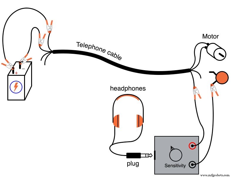
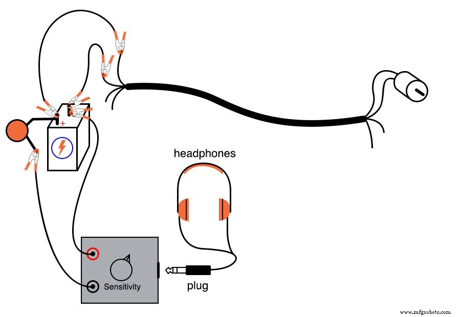
2. Place the audio detector across the motor terminals, inserting the 0.047 µF capacitor in series as shown:
3. You should hear a buzz or whine through the headphones – this is the AC noise generated by the brushes engaging the commutator.
The series capacitor acts as a high‑pass filter, allowing only AC to reach the detector while rejecting the DC component. Oscilloscopes employ the same principle for AC‑coupling: a capacitor is inserted in series with the probe.
4. In theory, the motor’s terminals should see pure DC because they are directly in parallel with the battery. However, internal battery resistance and the resistance of the cable conductors create voltage dips when the motor draws current pulses. These dips manifest as AC noise at the motor terminals:
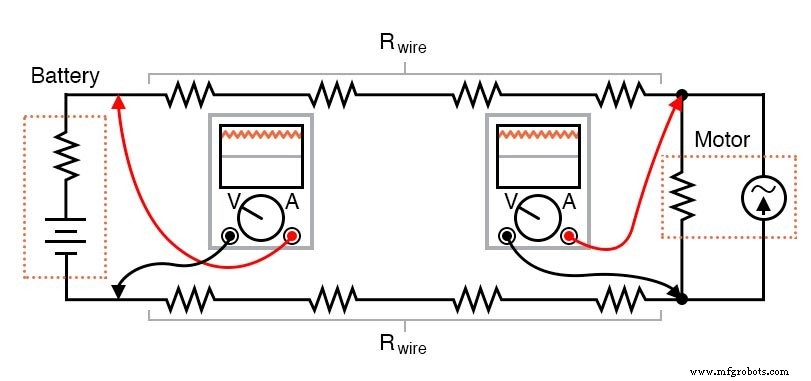
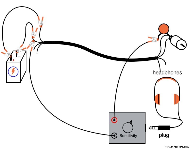
5. To verify, measure the noise voltage directly across the battery terminals with the audio detector. The smaller the resistance between the points, the lower the detected noise:
6. You can also measure the noise along a single telephone cable conductor by connecting the detector between its two ends. The noise arises from the current pulses flowing through that conductor’s resistance:
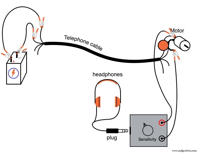
7. Next, explore how the AC noise couples to adjacent wires. Measure the voltage between one motor terminal and an unused cable conductor. No series capacitor is needed because no DC exists between these points:
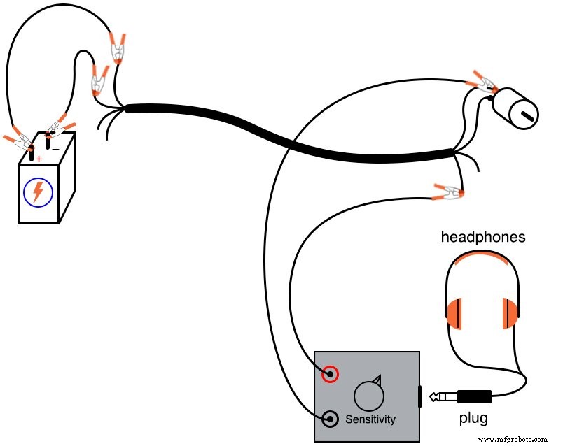
The detected voltage stems from stray capacitance between adjacent conductors, which provides a path for alternating current even though no charge flows through the capacitor itself.
Stray coupling can contaminate signals sent along an unused conductor, especially if that signal is sensitive to the induced noise.
Because capacitive coupling is stronger at higher frequencies, AC noise at higher frequencies will be more strongly coupled.
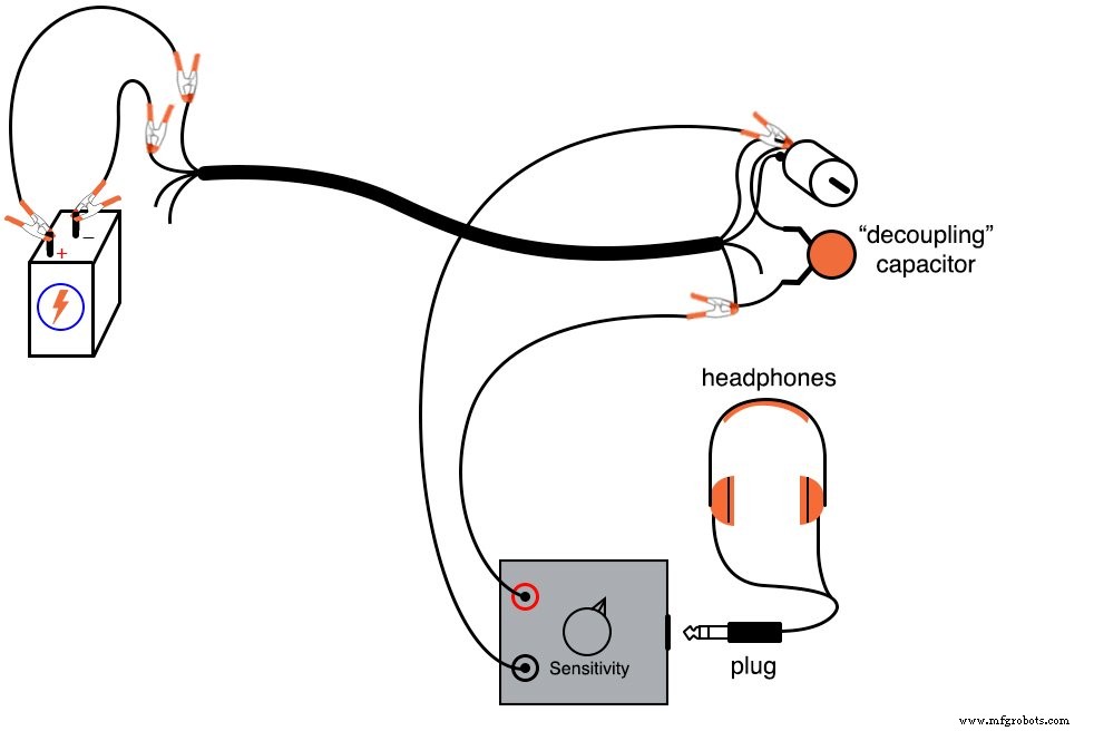
To mitigate noise on a DC signal, add a larger capacitor across the two conductors. The 0.22 µF capacitor serves as a decoupling capacitor, presenting a low impedance to AC while leaving DC unchanged:
7. Another effective strategy is to avoid sharing a common conductor between circuits. Measure the noise between the two unused conductors; it should be much lower because the stray capacitance couples nearly identical noise voltages to both conductors, cancelling out when the difference is taken:
Industrial Technology
- Understanding Logic Signal Voltage Levels: TTL vs CMOS
- Input & Output Coupling Techniques for Amplifiers: Capacitive, Direct, and Transformer Methods
- Voltage‑to‑Current Signal Conversion: A Practical Transconductance Amplifier Design
- Voltage Signal Systems: Accurate Measurement of Water Tank Levels
- Tachogenerators: Precision Speed Measurement for Industrial Motors and Equipment
- Understanding AC Waveforms: Sine Waves, Frequency, and Oscilloscope Basics
- Variable Reluctance Motors: Types, Operation, and Applications
- Advanced DC Motor Speed Control: Voltage, Rheostatic, and Flux Techniques
- The Definitive Guide to Choosing Motor Couplings for Long-Lasting Performance
- Capacitive Coupling Explained: Energy Transfer in Electronic Circuits