


Constructing a Resonant Tank Circuit: Inductor, Capacitor, and Practical Insights
PARTS AND MATERIALS
- Oscilloscope (high‑voltage compatible)
- Non‑polarized capacitors (0.1 µF–10 µF)
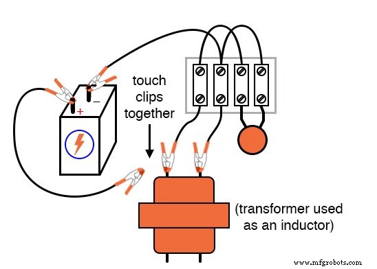
- Step‑down power transformer (120 V / 6 V) – use only one winding as an inductor
- 10 kΩ resistors
- 6‑V battery
The transformer functions solely as an inductor; leave the unused winding open. If a dedicated choke is available, it can replace the transformer, but chokes are less common in hobby kits.
CROSS‑REFERENCES
Lessons In Electric Circuits, Volume 2, chapter 6: “Resonance”
LEARNING OBJECTIVES
- Build a resonant tank circuit
- Understand how capacitor value influences resonant frequency
- Learn to introduce antiresonance (damping) into the circuit
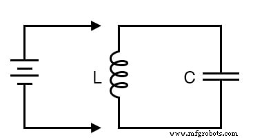
SCHEMATIC DIAGRAM
ILLUSTRATION
INSTRUCTIONS
Connect an inductor and a capacitor in parallel. Briefly energize the network with a DC source (battery). The stored energy shuttles between the capacitor’s electric field and the inductor’s magnetic field, producing damped oscillations. Observe the waveform on an oscilloscope wired across the tank.
Safety Note: Avoid using a PC or sound card as the oscilloscope. Inductive kickback can generate voltages that easily damage sensitive audio inputs.
The natural (resonant) frequency of a tank circuit is given by:
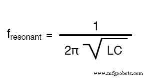
For many small power transformers, the primary winding inductance is about 1 H; use this as a starting point when estimating oscillation frequency. Higher‑Q inductors will sustain oscillations longer.
Experiment by varying the capacitor value. Record the resulting frequency shifts and decay times. With a known capacitance (from a meter) and measured resonant frequency (from the oscilloscope), you can rearrange the formula to solve for inductance:
$$L = \frac{1}{(2\pi f)^2 C}$$
Adding intentional resistance—either in series or parallel—introduces antiresonance, damping the oscillations similarly to a car’s shock absorber.
COMPUTER SIMULATION
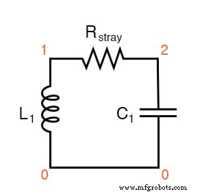
The schematic includes a stray resistor (Rstray) to mimic real‑world losses. Lowering Rstray prolongs the decay, while removing it leads to perpetual oscillation.
Netlist for SPICE Simulation
tank circuit with loss l1 1 0 1 ic=0 rstray 1 2 1000 c1 2 0 0.1u ic=6 .tran 0.1m 20m uic .plot tran v(1,0) .end
RELATED WORKSHEETS
- Resonance Worksheet
- Passive Filter Circuits Worksheet
- Oscillator Circuits Worksheet
Industrial Technology
- Circuit With a Switch: A Practical Guide to Basic Electrical Circuits
- Voltage Follower Amplifier: Design, Build, and Measurement Guide
- Mastering AC Circuit Equations: Impedance, Reactance & Resonance
- Getting Started with SPICE: A Text‑Based Circuit Simulation Tool
- Mastering SPICE Netlist Syntax: Component Naming, Passive & Active Elements, and Source Definitions
- Demultiplexers Explained: How They Route Signals in Digital Circuits
- Understanding TRIACs: Bidirectional Power Control in AC Applications
- Understanding Electrical Resistance and Circuit Safety
- Understanding Fuses: Types, Ratings, and Safe Installation
- Parallel Tank Circuit Resonance: Theory, Calculations, and SPICE Verification