Build an Ultra‑Sensitive EMF Detector with Arduino Nano
Components and supplies
Arduino Nano R3
×
1
Adafruit Standard LCD - 16x2 White on Blue
×
1
Buzzer
×
1
LED (generic)
×
1
Toggle Switch, Toggle
×
1
Apps and online services
Arduino IDE
About this project
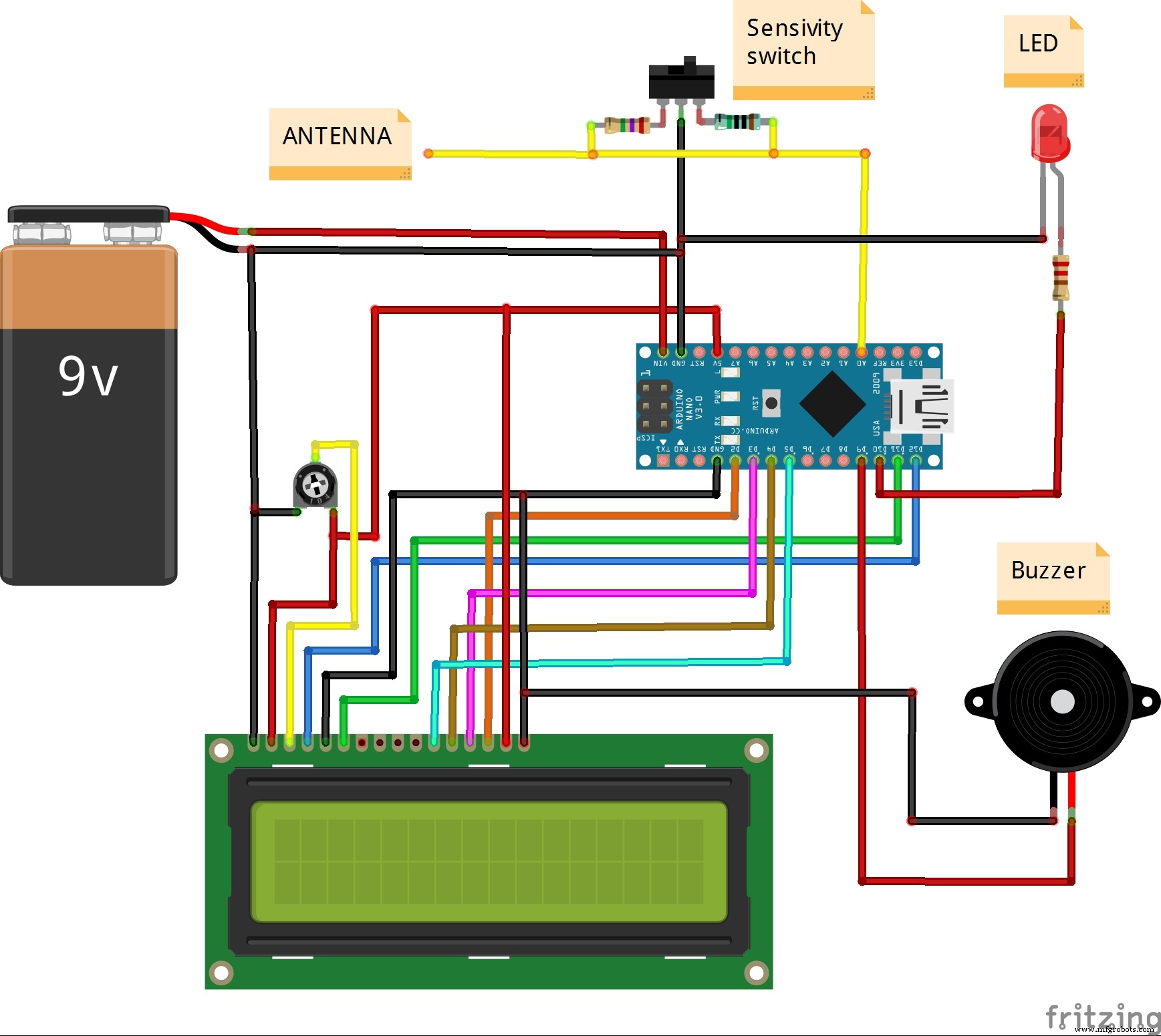
This is a simple device capable of detecting very weak electromagnetic fields. The relative field intensity is displayed on the LCD display and at the same time are given a buzzer sound signalization and LED light signalization. In this case the sensor is a plain copper wire, with a 1.5mm diameter, but you can use any piece of wire or metal tile. Sensitivity can be adjusted via code, and also by changing the value of the resistor connected between A0 and grounding. With the help of a switch, one of the two values of the resistor is selected, and thus the degree of sensitivity of the device. So we can easily calibrate it, by comparing it to a recalibrated industrial device.
As can be seen below the circuit is very simple and consists of Arduino Nano microcontroller and several external components.
The code is a combination of two parts (Arduino based VU meter by KTAudio for LCD display part, and Aaron ALAI EMF Detector for sensor part) and also modifications to certain parts of it for the purpose of greater stability of the whole device. You can download it on link given below.
As you can see in the video, this device can easily detect electromagnetic fields generated by power cables that are only under voltage and not connected to a consumer. For example, an electromagnetic field from an old CRT monitor can be detected at a distance of 3m and more.
The detector is mounted in a convenient housing and is powered by a 9V battery.
Code
Code
CodeC/C++
/*
  Arduino based VU meter by KTAudio.
  Developed by ThomAce (Tamas Kamocsai) based on siemenwauters, theredstonelabz and michiel H's VU meter.

  GNU GPL License v3

  Developer: ThomAce (Tamas Kamocsai)
  Mail: thomacepcg@gmail.com
  Version: 1.0
  Last modification date: 2019.09.24

  Original version:
  https://www.instructables.com/id/ARDUINO-VU-METER/

  Original description:
  VU meter by siemenwauters, theredstonelabz and michiel H don't forget to like and subscribe to support my work. tnx

  Modified by mircemk (Mirko Pavleski)
*/

#include <LiquidCrystal.h>

byte Bar[8] = {
        B11111,
        B00000,
        B11111,
        B11111,
        B11111,
        B11111,
        B00000,
        B11111
};

byte L[8] = {
        B00111,
        B01000,
        B10100,
        B10100,
        B10100,
        B10111,
        B01000,
        B00111
};

byte R[8] = {
        B00111,
        B01000,
        B10110,
        B10101,
        B10110,
        B10101,
        B01000,
        B00111
};

byte EndMark[8] = {
        B10000,
        B01000,
        B00100,
        B00100,
        B00100,
        B00100,
        B01000,
        B10000
};

byte EmptyBar[8] = {
        B11111,
        B00000,
        B00000,
        B00000,
        B00000,
        B00000,
        B00000,
        B11111
};

byte peakHoldChar[8] = {
        B11111,
        B00000,
        B01110,
        B01110,
        B01110,
        B01110,
        B00000,
        B11111
};

String main_version = "1.0";
int  right;                        //Variables to store and calculate the channel levels
const int numReadings = 5;              //Refresh rate. Lower value = higher rate. 5 is the defaul

int indexR = 0;
int totalR = 0;
int maxR = 0;

int inputPinR = A0;                     //Input pin Analog 0 for RIGHT channel

int volR = 0;
int rightAvg = 0;

long peakHoldTime = 100;               //peak hold time in miliseconds
long peakHold = 0;
int rightPeak = 0;

long decayTime = 0;
long actualMillis = 0;
int pin10 = 10;         // output of red led
int val = 0;
int pin9 = 9;
LiquidCrystal lcd(12, 11, 5, 4, 3, 2);  //lcd configuration

void setup()
{
  lcd.begin(40, 2); //Setting up LCD. 16 chars and 2 rows

  lcd.createChar(1, Bar);

  lcd.createChar(3, R);
  lcd.createChar(4, EmptyBar);
  lcd.createChar(5, EndMark);
  lcd.createChar(6, peakHoldChar);

  //Showing loading  message and loading bar

  String KTAudio = "    MIRCEMK";

  for (int i = 0; i <= 16; i++)
  {
    lcd.setCursor(0, 0);
    lcd.print(KTAudio.substring(0, i));
    delay(50);
  }

  KTAudio = "  EMF-detector " + main_version;

  for (int i = 0; i <= KTAudio.length(); i++)
  {
    lcd.setCursor(0, 1);
    lcd.print(KTAudio.substring(0, i));
    delay(50);
  }

  delay(500);

  lcd.clear();
  lcd.setCursor(0, 0);
  lcd.print("Loading...");

  for (int i = 0; i < 16; i++)
  {
    lcd.setCursor(i, 1);
    lcd.write(4);
  }

  for (int i = 0; i < 16; i++)
  {
    lcd.setCursor(i, 1);
    lcd.write(1);

    delay(50);
  }

  delay(500);
  lcd.clear();

  decayTime = millis();
}

void loop()
{
   lcd.setCursor(0, 0);
   lcd.write(" EMF-intensity");
  actualMillis = millis();


  lcd.setCursor(0, 1);        //R channel index
  lcd.write(3);               //R symbol

  lcd.setCursor(15, 1);       //closing tag / end mark index 2
  lcd.write(5);               //closing tag / end mark


  totalR = analogRead(inputPinR) ;


   if(totalR >= 1){
    totalR = constrain(totalR, 0, 100);               // mess with these values
    totalR = map(totalR, 0, 100, 1, 255);        // to change the response distance of the device
    analogWrite(pin10, totalR);                 // *note also messing with the resistor should change
    analogWrite(pin9, totalR);                                                             // the sensitivity
   }else{                                                     // analogWrite(pin10, val); just tuns on the led with
                                                                  // the intensity of the variable val
    analogWrite(pin10, 0);                     // the else statement is just telling the microcontroller
    analogWrite(pin9, 0);                                                             // to turn off the light if there is no EMF detected
   }
  if(totalR > maxR)
  {
    maxR = totalR;
  }

  indexR++;

  if (indexR >= numReadings)
  {
    indexR = 0;
    right = maxR;
    maxR = 0;
  }

  volR = right / 3;

  if(volR > 14)
  {
    volR = 14;
  }

  if (volR < (rightAvg - 2))
  {
    if (decayTime < actualMillis)
      rightAvg--;

    volR = rightAvg;
  }
  else if (volR > (rightAvg + 2))
  {
    volR = (rightAvg + 2);
    rightAvg = volR;
  }
  else
  {
    rightAvg = volR;
  }

  if (volR > rightPeak)
  {
    rightPeak = volR;
  }

  drawBar(volR, rightPeak, 1);


  if (decayTime < actualMillis)
    decayTime = (millis() + 50);

  if (peakHold < actualMillis)
  {
    peakHold = (millis() + peakHoldTime);
    rightPeak = -1;

  }
}

void drawBar(int data, int peakData, int row)
{
  //If the previous peak data is 1 or 0, then not taking care of the value.
  if (peakData < 2)
  {
    peakData = -1;
  }

  //First char (idx 0) = R or L
  //Last (16th) char (idx 15) is the closing mark of the bar.
  //We have 14 chars to write.
  for (int col = 1; col < 15; col++)
  {
    lcd.setCursor(col, row);

    if (col < data)
    {
      lcd.write(1); //write bar element
    }
    else if (peakData == col)
    {
      lcd.write(6); //write the peak marker
    }
    else
    {
      lcd.write(4); //write "empty"
    }
  }
}