


IC 4017 (CD4017) – Specs, Features & Application Guide
As modern-day digital electronics evolve daily, therefore, prompting us to learn about relevant integrated circuits.
Integrated circuits are critical components for every electronic device used today. Maybe, with the increase in demand, maybe you might want to make your Circuit Boards. This article is going to talk about IC 4017/ CD4017. IC 4017 is one of the entry-level integrated circuits that form part of the circuit board. Therefore, understanding these integrated circuits allows you to move on more significant projects and make more complicated circuit boards.
IC 4017 Decade Counter
The CD4017 IC is a Complementary metal-oxide-semiconductor(CMOS) Decade counter thus used in low-range counting applications. CD4017 IC reduces Integrated circuit IC space while also separating its outputs. The CD4017 IC counts from 0 to 10 hence the name decade.
CD4017 is not a standard ring counter, meaning it does not trigger all flip flops at the same time. Therefore, it uses the Johnson counter technique to achieve flip flop count.
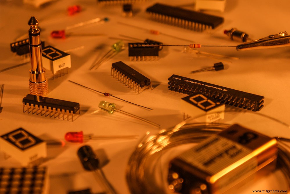
(integrated circuit)
4017 Pin Configuration of IC 4017
IC 4017 has 16 pins, and below are their functions.
- Pin-1-7,9-11: Output pin(s) – Hence, Qy moves high when the counter reads y.
- Pin-8: Ground pin – it’s a LOW voltage (0V) connection.
- Pin-12: Carry pin – every ten clock input cycles, it completes one cycle hence, one clock cycle. It connects one or more CD 4017 ICs in the circuit.
- Pin-13: Enable – It’s a low active enable pin, therefore, allowing for counting.
- pin-14: Clock pin – Integrated circuit IC counts the rising edges applied to this input and registers it as 1.
- Pin 15: Reset pin – Reset pin is set to low voltage during normal operation. Consequently, to reset the integrated circuit IC, it’s exposed to high voltage.
- Pin 16: Vcc – Connected to a supply voltage that ranges from 3V to 15V.
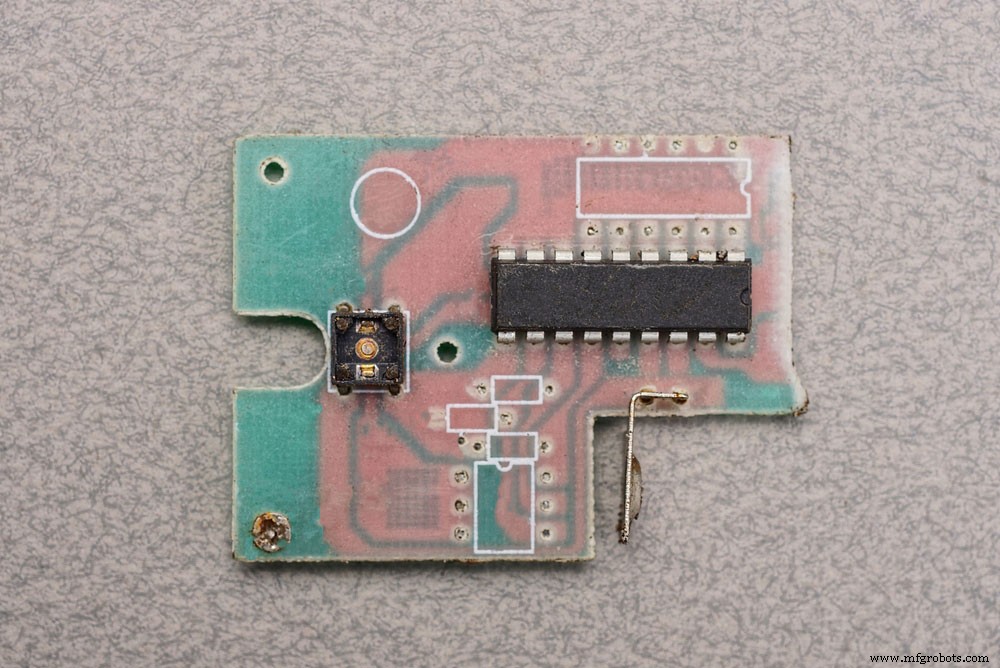
(IC 4017 connected to an IC)
Features and specifications of IC 4017
IC 4017 has many features that make it desirable for low applications requiring integrated circuit IC. Some of these types of equipment include medical equipment and mechanical counters, just to mention a few. Here are some of the features that make IC 4017 so widely used.
- Noise immunity is high, typically 0.45 VDD
- Operation is completely static
- TS or Storage Temperature ranges from −65°C to +150°C
- It has a 700 mW Power Dissipation, and its Dual-In-Line is
- The IC 4017 has a wide supply voltage range from 3V to 15V power.
- IC 4017 has well-matched compatibility with Transistor-Transistor Logic.
- IC 4017 has an operational speed or clock speed of 5 MHz.
- It provides a decoded tenten, output pin support system.
- It has different packages such as 16-pin PDIP, PDSO, and GDIP.
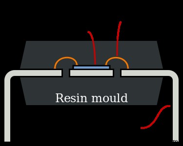
(Side view of Double Line In-Package (DIP) IC)
Application of IC CD4017
Several applications use CD4017 Binary counters. Some of the applications using CD4017 integrated circuit IC include:
- 3X3 LED cube circuits
- Police lights circuits
- Clapping on and off switch circuit
- Digital dice circuits
- Washroom automatic lights control
- Adjustable Timer circuits
- LED Running Lights
- Automotives
- Alarms
- Electronic production of medical equipment and instrument devices
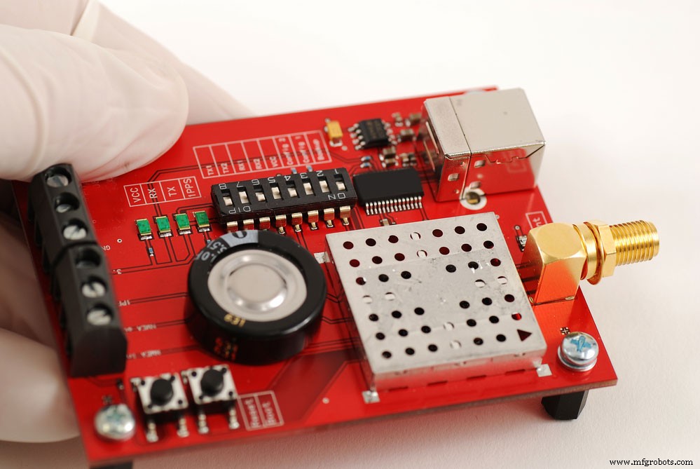
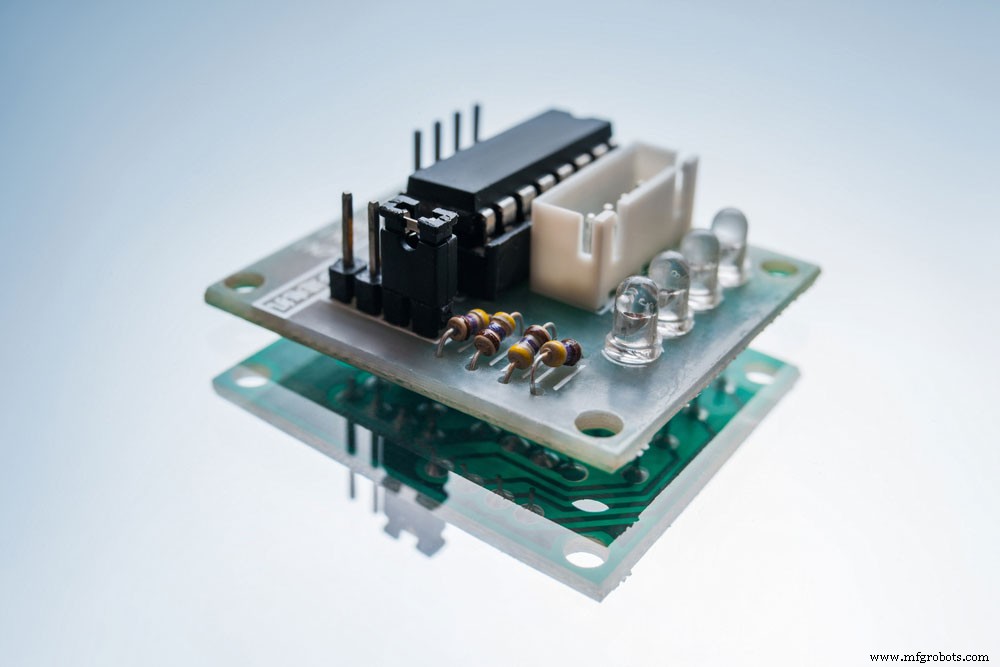
(Electronic board made with CD4017)
How to use CD4017?
The CD4017 pinout needs a 3V to 15V power supply. However, most versions of the CD4017 pinout support a power supply of +5V. Some CD4017 pinouts like HEF4017 use up to 15V.
The Vcc (Voltage Common Collector) or Vdd (Voltage Drain Drain) pin is where the power supply connects to the CD4017 IC, and the Ground pin connects to the ground. Subsequently, the ten output pins connect to the load, which is mostly an LED display.
CD4017 pinout counts from 0 to 9 (Q0 to Q9) whenever it senses a high clock pulse from Clock input (pin 14).
Subsequently, we need a timer circuit to generate a clock pulse and keep the clock source ticking. Arduino and the 555 timers are some of the timer circuits that the circuit can use. The timers generate custom pulses using input-output(I/O) pins. Sequential output changes from pin Q0 to Q9 can get pulse interruption from two pins namely: the Clock Enable(pin 13) and the reset pin (pin 15) pins.
These pins are ground pins by default and hold low(0V) voltage charges. Clock Enable when set to high pauses the count. For example, when the count is at the 7th output, and you press Clock Enable, the count will remain at the 7th output until Clock Enable is set to low again. CD4017 pinout then continues the count from where it stopped and continues. Reset pin when set to high the Reset signal calibrates the count back to zero. For example, if the count is Q8 and Device Reset is pressed, the count moves back to Q0.
The Carry Out pin (pin 12) stays low(0V) by default. When the integrated circuit IC completes its 10th count, the pin goes high and remains high till the 5th count. It will count another five counts and then move low and turn on again when the count reaches ten.
(CD4017 circuit components)
Example LED sequencer/light tracker using 4017 IC
- Components of the sequencer circuit hardware
- Two ten kΩ resistors
- One,kΩ resistor
- One 4.7 μF polarised capacitor
- LED lights
- Timer IC 555
- PC817 Photocoupler
- IC 4017
- sequencer circuit
(well-connected LED sequencer circuit.)
- Circuit operating
The 555 timers operate as Astable mode in the sequencer circuit to produce the clock pulse required by the CD4017 pinout IC. Photocoupler simultaneously converts electrical signals to light signals.
The input clock signal of CD4017 connects to the Astable timer output.
The clock signal produces a stream of pulses, thus increasing the counter/clock cycle by 1. This, in turn, Lights the LED display one by one while subsequently turning them off before the next LED turns on.
Summary
To summarize, this article looks at the internal elements, application, and functionality of the CD4017 chip. Chip circuit connection is also explained to discuss how real-world circuit board applications work. If you have any questions, please feel free to contact us. We will be more than happy to help.
Industrial Technology
- Build an LED Sequencer with 555 Timer & 4017 Counter – Frequency Division & Debounce
- Decoding Numbers and Symbols in Electronics
- Analyzing a Parallel R‑L‑C Circuit: Impedance, Current, and SPICE Simulation
- Analyzing Series-Parallel RC and RL Circuits with Complex Impedance
- Comprehensive Summary of Resistors, Inductors, and Capacitors in AC Circuits
- Transformers with Multiple Windings: From Taps to Variacs – A Comprehensive Guide
- Three‑Phase Y and Delta Configurations: Design, Analysis, and Reliability
- Expert Guide to Hall Effect Current Sensors: Open‑Loop & Closed‑Loop Configurations
- Optimizing Hall Effect Position Sensing: Head‑On vs. Slide‑By Magnetic Configurations
- Harnessing Automation in Manufacturing: Boost Efficiency & Cut Labor Costs