


Optimizing Hall Effect Position Sensing: Head‑On vs. Slide‑By Magnetic Configurations
Learn how Hall effect sensors drive precise position sensing
Hall effect sensors convert magnetic field strength into accurate location data, making them indispensable for modern position‑sensing systems. By attaching a small permanent magnet to a moving part, the sensor can detect shifts in the magnetic field as the magnet travels relative to the sensor, allowing real‑time determination of position.
Multiple sensor‑magnet layouts exist, each manipulating the magnet’s motion to produce a distinct magnetic signature at the sensor. These variations directly influence the sensor’s response characteristics and suitability for specific applications.
In this article we examine the two most common configurations—head‑on and slide‑by—highlighting their design principles, advantages, and limitations to help you choose the right approach for your project.
Head‑On Configuration
The simplest layout is the head‑on arrangement shown in Figure 1. Here the magnet’s south pole moves directly toward or away from the sensor’s active area.
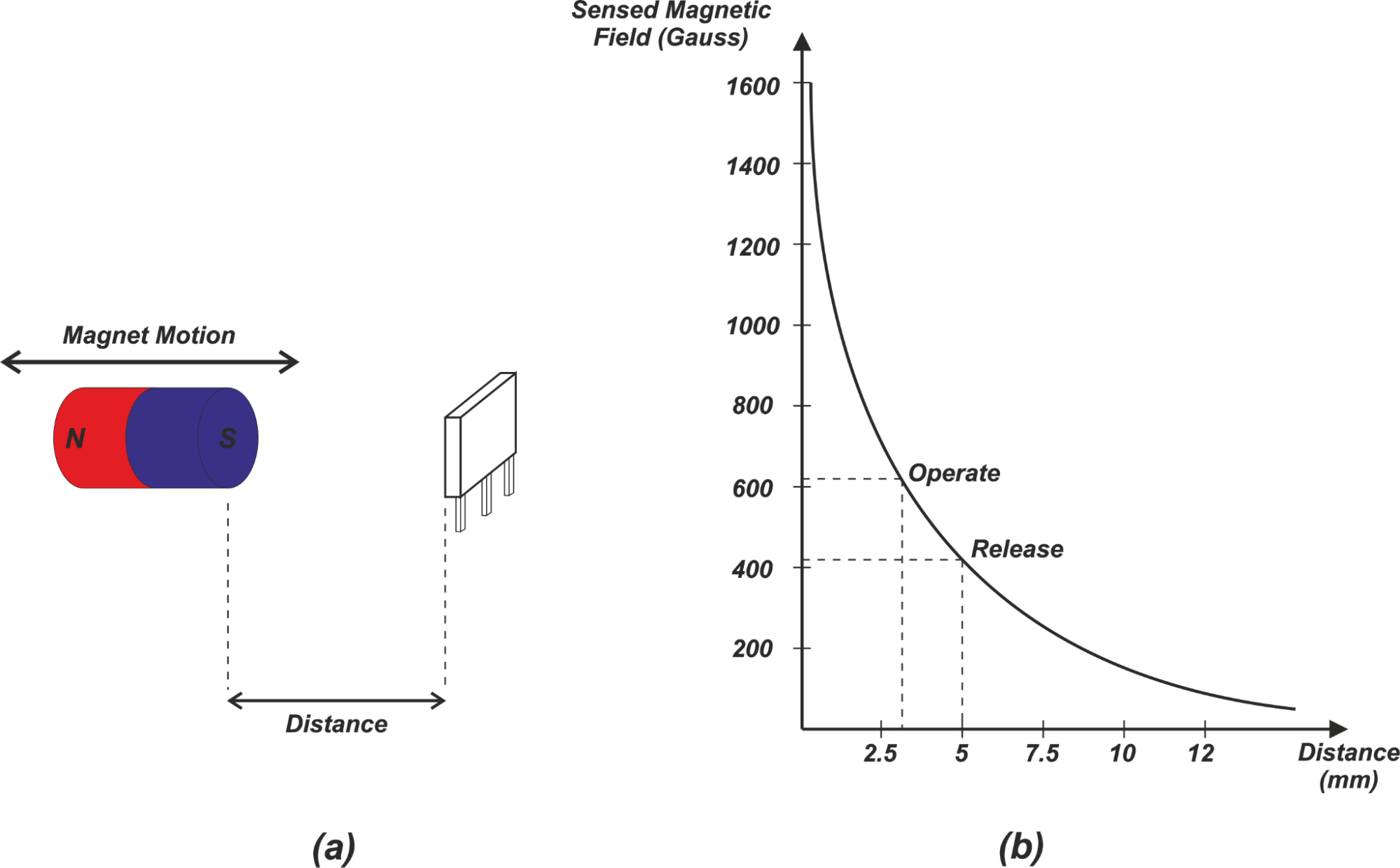
Figure 1.
When the magnet is very close, a large number of magnetic flux lines intersect the sensor, producing a high field. As the pole recedes, the field drops sharply, following an inverse‑square law (Gauss vs. distance). The values plotted in Figure 1(b) correspond to a roughly 30 mm long, 6 mm diameter magnet.
Application: Detecting the Presence of an Object
In a head‑on setup, a digital (ON/OFF) Hall sensor can serve as a proximity detector. The sensor’s "operate" point (field strength at which it turns on) and "release" point (field strength at which it turns off) define two thresholds. For the example in Figure 1(b), the operate point is ~620 Gauss at 3.1 mm, while the release point is ~420 Gauss. As the magnet approaches, the field rises above the operate threshold and the sensor stays ON; it remains ON until the field falls below the release threshold, effectively signaling the object’s presence.
Limitations of Head‑On Sensing
Because the Gauss‑distance curve flattens near the release point, small variations in the release threshold can cause significant uncertainty in the OFF distance. Conversely, variations near the operate point have a smaller effect. Figure 2 illustrates this sensitivity: Δd1 (operate) is much smaller than Δd2 (release).
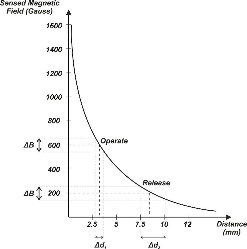
Figure 2.
Additional drawbacks include rapid field decay—making large‑stroke detection difficult—and a nonlinear field‑distance relationship that complicates linear position measurement. Consequently, head‑on sensing is best suited for proximity detection where high precision is not critical.
Unipolar Slide‑By Sensing
In a slide‑by configuration, a single magnet pole moves laterally across the sensor’s surface, maintaining a constant perpendicular distance (the "air gap"). Figure 3(a) depicts this motion.
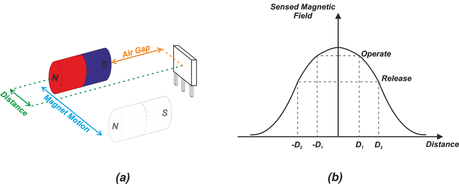
Figure 3.
The field peaks when the pole is centered (distance = 0) and symmetrically decreases as the pole moves away. This symmetry ensures that the operate and release points are identical whether the magnet approaches or retreats, which is advantageous for detecting deviations from a central path.
Figure 4 shows how the peak flux varies with different air‑gap distances.
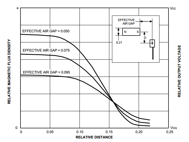
Figure 4. Image courtesy of Allegro.
Head‑On or Slide‑By?
Choosing between these configurations depends on the nature of the motion and mechanical constraints. Head‑on sensing is ideal when the object has a fixed endpoint and only its presence/absence matters—think of a smartphone case opening or closing. Slide‑by sensing, with its lateral motion capability, is suitable when the object may pass the sensor or when a symmetric response around a central line is required.
While other slide‑by variations exist that break the symmetry, the basic unipolar layout offers predictable behavior and straightforward implementation.
Stay tuned for our next article, where we’ll explore advanced magnetic configurations commonly used in Hall effect position sensing.
To see a complete list of my articles, please visit this page.
Sensor
- Compass Sensors: From Ancient Navigation to Modern Devices
- Magnetic Sensors: Principles, Types, and Applications
- Hall Effect Sensors: Working Principles & Practical Applications
- Expert Guide to Hall Effect Current Sensors: Open‑Loop & Closed‑Loop Configurations
- Digital Hall‑Effect Sensors: Unipolar, Omnipolar, Bipolar, and Latch Switches Explained
- Linear Hall‑Effect Position Sensing: Optimizing Linearity and Slope in Slide‑By Configurations
- Understanding the Hall Effect and How Hall Effect Sensors Operate
- Hall Effect Sensor Pinout Explained: A Complete Reference
- YF-S201 Hall Effect Water Flow Sensor: Pinout, Features & Practical Applications
- Mastering Hall Effect Sensors: Principles, Applications, and Design