


Digital Hall‑Effect Sensors: Unipolar, Omnipolar, Bipolar, and Latch Switches Explained
Understanding Hall‑Effect Switches and Latches: Polarity, Hysteresis, and Practical Applications
Hall‑effect devices are precision magnetic field comparators. They evaluate the magnetic flux density—commonly called the B‑field—against predefined thresholds and output a binary result. The four principal categories of digital (on/off) Hall sensors are unipolar switches, bipolar switches, omnipolar switches, and latches.
Before diving into each type’s transfer function, it’s essential to clarify the concept of B‑field polarity—a recurring theme throughout our discussion.
Defining B‑Field Polarity
A Hall sensor is inherently directional; it senses only the component of the magnetic flux density that aligns with its sensitivity axis. Figure 1 illustrates the sensitivity axes of two common sensor packages.
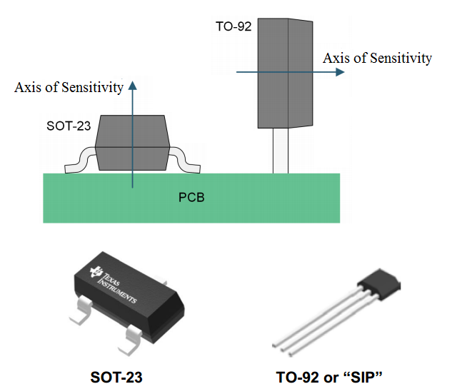
Figure 1. Courtesy of Texas Instruments.
If the applied magnetic field produces a component along the sensitivity axis, the B‑field is considered positive. Conversely, a component opposite to the axis is negative. Figure 2 demonstrates a scenario where the sensor at location A experiences a negative B‑field.
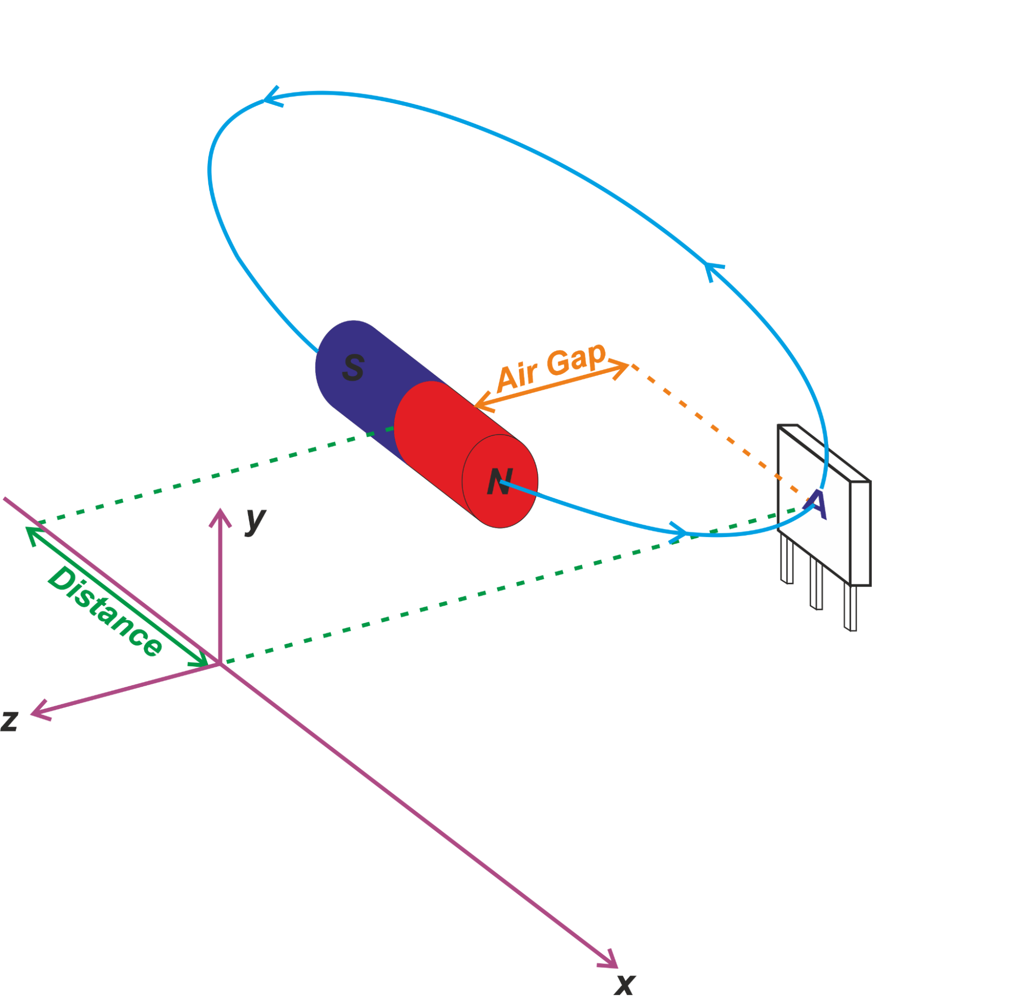
Figure 2.
Assuming the sensor’s sensitivity axis aligns with the z‑axis, the magnetic field lines of a magnet—originating at the north pole and terminating at the south pole—create a negative B‑field at the sensor. Many manufacturers adopt a convention: a south pole facing the sensor’s branded (front) face generates a positive B‑field, while a north pole yields a negative B‑field. This convention holds only when the magnet’s poles face the branded side; reversing the orientation invalidates it.
Most Hall devices are one‑dimensional, sensing along a single axis, but multi‑element ICs can provide three‑axis sensitivity.
Unipolar Switches
Figure 3 depicts the operation of a unipolar switch.
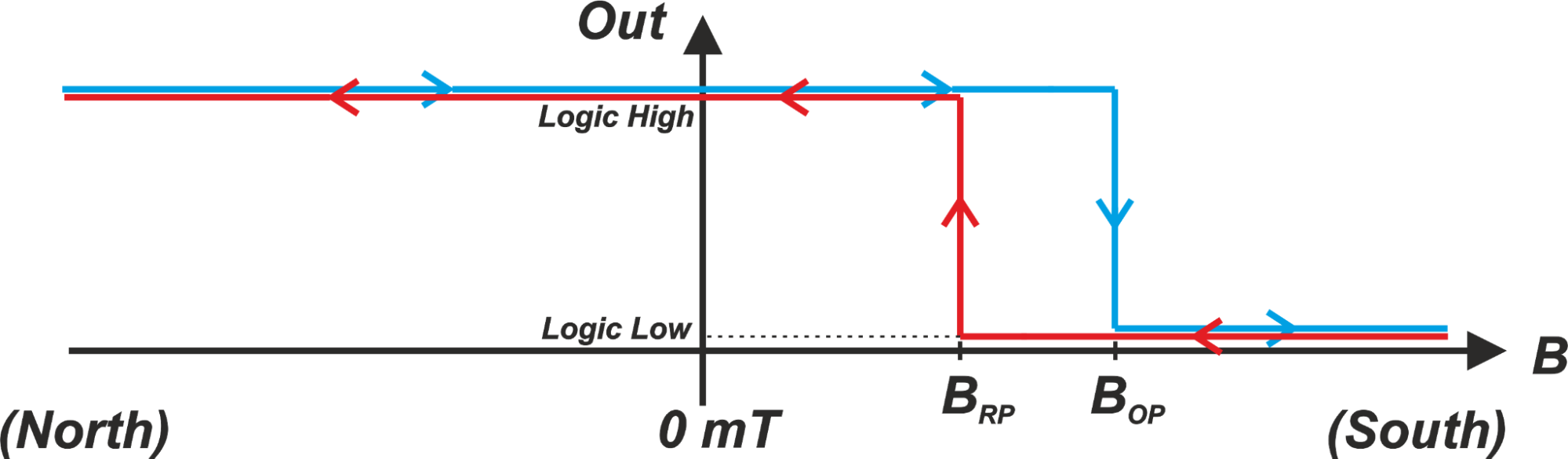
Figure 3.
Its thresholds—BOP (operate point) and BRP (release point)—lie exclusively in the positive B‑field region. The sensor responds only to a south‑pole (positive) field; a north‑pole (negative) field has no effect, hence the term “unipolar.”
When a north‑pole field is applied and the field strength increases toward the positive direction, the sensor remains off (logic high) until the applied B exceeds BOP. At that instant, the output flips to logic low. If the field then decreases, the sensor stays on until the B falls below BRP, at which point it reverts to logic high. This asymmetric thresholding introduces hysteresis, preventing rapid output fluctuations caused by mechanical vibrations or electromagnetic noise, as illustrated in Figure 4.
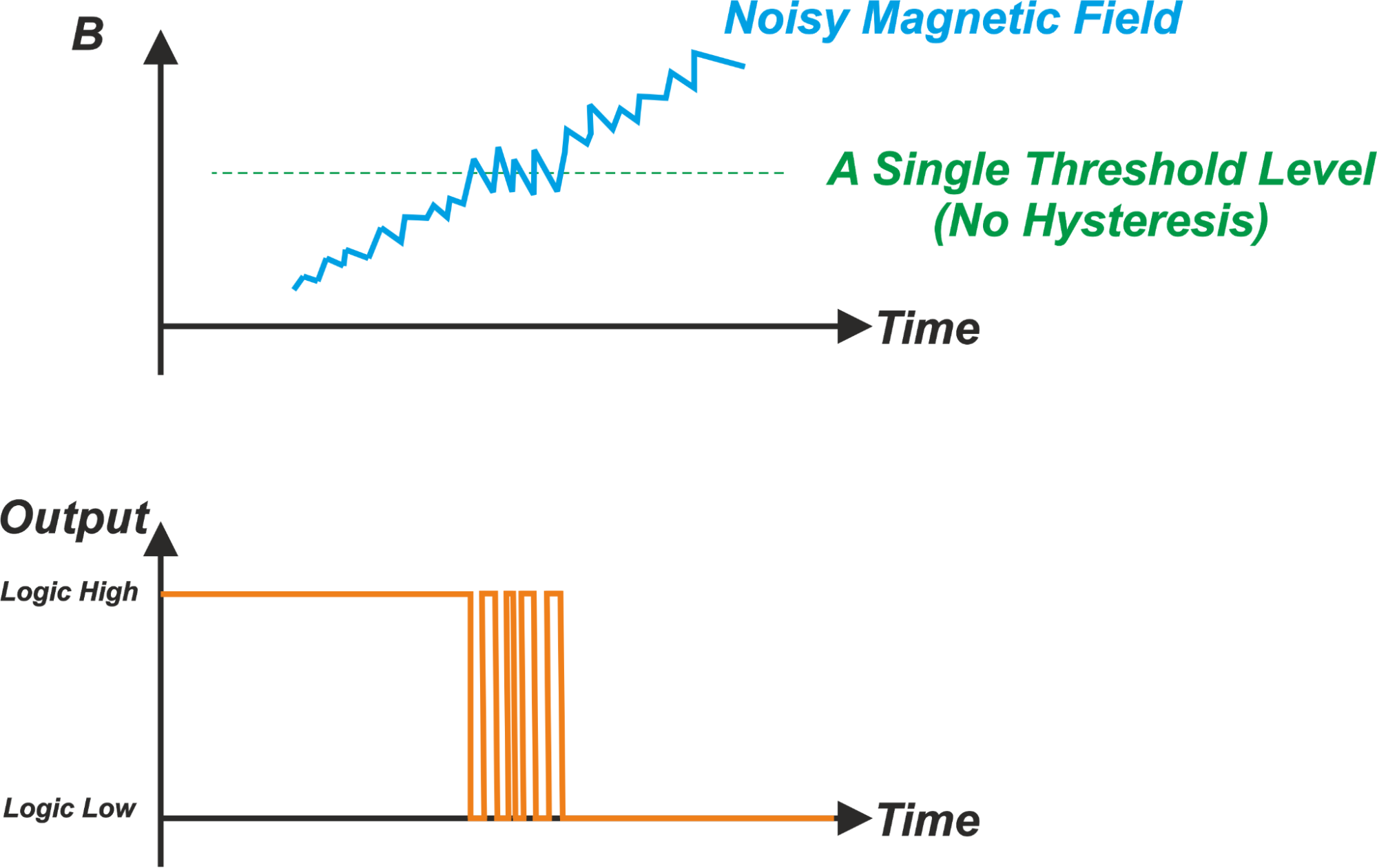
Figure 4. Without hysteresis, the output can be indeterminate around the threshold.
The hysteresis width is defined as BHYS = BOP – BRP. Depending on the sensor’s internal circuitry, the logical states of the output may be inverted, but the switching behavior remains identical.
Omnipolar Switches
Omnipolar switches activate when the magnetic field magnitude exceeds a threshold, regardless of polarity. Figure 5 shows the transfer function.
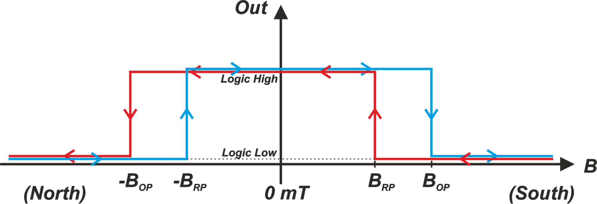
Figure 5.
When |B| > BOP, the sensor turns on (logic low). When |B| < BRP, it turns off (logic high). The same magnitude of BOP and BRP applies to both positive and negative fields, providing symmetric operation.
Hall‑Effect Latches
Figure 6 illustrates a latch’s behavior.
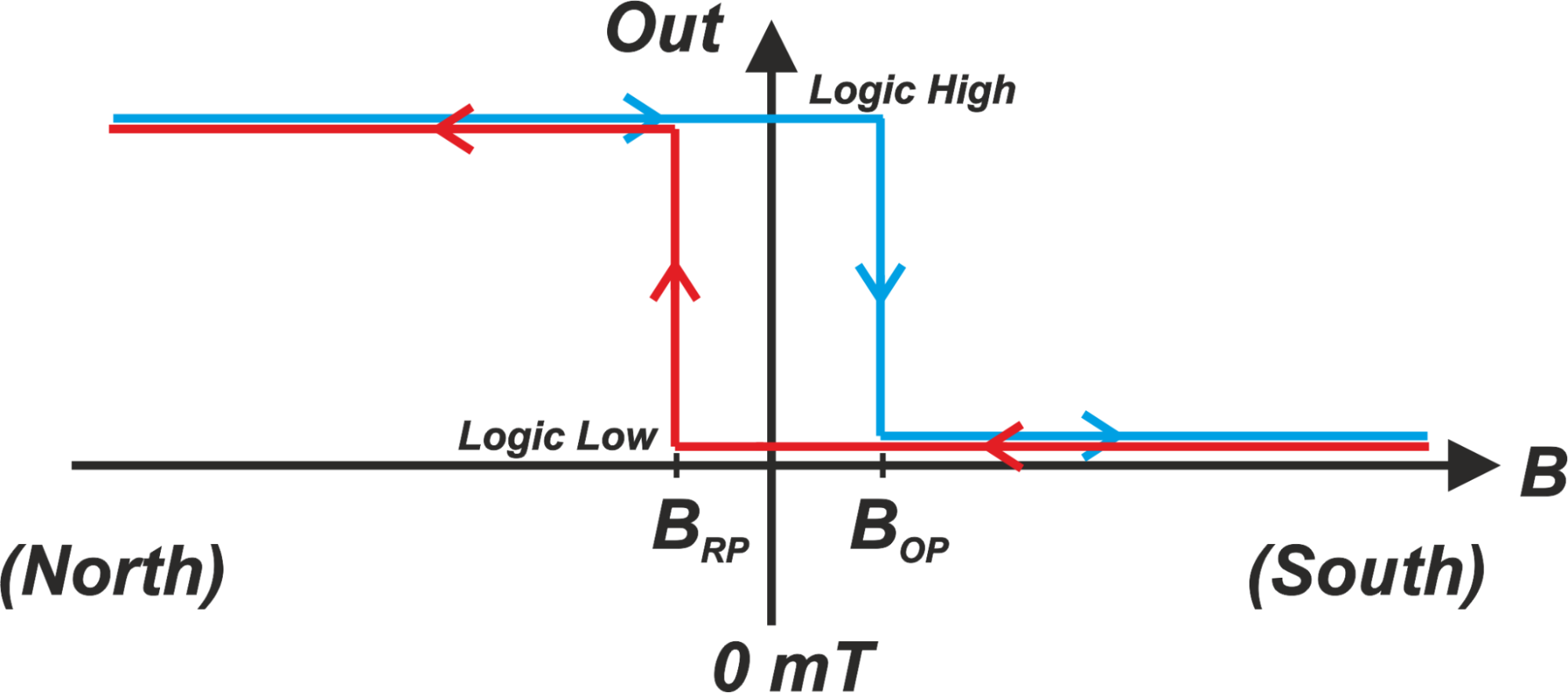
Figure 6.
A latch features a positive BOP and a negative BRP. It turns on when B > BOP and turns off when B < BRP. Between these thresholds—i.e., the hysteresis region spanning BRP to BOP—the output remains unchanged, even if the field passes through zero. Consequently, the latch “holds” its state until a field of opposite polarity and sufficient magnitude is applied.
Because a latch senses both the magnitude and polarity of the B‑field, it is ideal for rotary applications where a ring magnet’s polarity alternates, as shown in Figure 7.
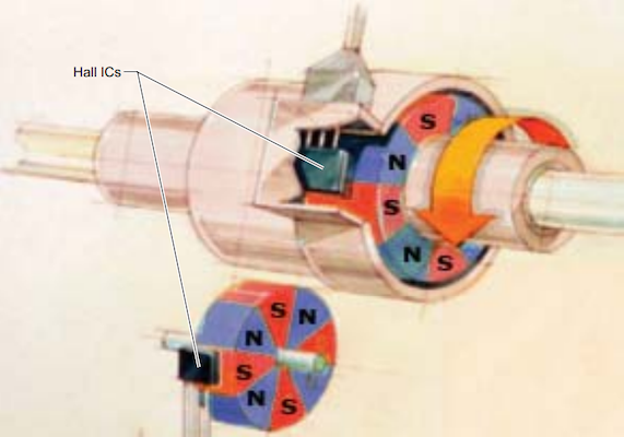
Figure 7. Courtesy of Allegro.
For latches, the operate and release points are equal in magnitude but opposite in sign (BOP ≠ –BRP).
Bipolar Switches
Bipolar switches provide a maximum BOP and a minimum BRP, but the exact threshold values can vary from unit to unit. Figure 8 presents three sample responses from a single manufacturing lot.
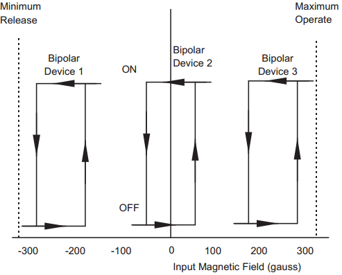
Figure 8. Courtesy of Honeywell.
Device 1 and Device 3 both have thresholds of the same polarity (both negative or both positive), whereas Device 2 exhibits a latch‑like response with a positive BOP and negative BRP. According to Allegro’s “Bipolar Switch Hall‑Effect IC Basics” note, only about 10 % of bipolar switches resemble Devices 1 or 3; the majority display latch‑type behavior.
While a bipolar switch can offer a narrower hysteresis band (BHYS = BOP – BRP) and higher sensitivity than a latch, its unit‑to‑unit variability requires careful design to ensure robust operation across the specified threshold range.
For more in‑depth coverage, explore the full collection of our technical articles.
Sensor
- Electromagnetism: From Oersted’s Discovery to Modern Applications
- Understanding Magnetic Fields and Inductance: Principles, Applications, and Design
- Compass Sensors: From Ancient Navigation to Modern Devices
- Hall Effect Sensors: Working Principles & Practical Applications
- Expert Guide to Hall Effect Current Sensors: Open‑Loop & Closed‑Loop Configurations
- Linear Hall‑Effect Position Sensing: Optimizing Linearity and Slope in Slide‑By Configurations
- Optimizing Hall Effect Position Sensing: Head‑On vs. Slide‑By Magnetic Configurations
- Microchip Unveils 90W PoE Boosters for Legacy and IEEE Devices Without Changing Switches
- Understanding the Hall Effect and How Hall Effect Sensors Operate
- Advanced Magnetic Field Detection with NASA’s Fiber Bragg Grating Technology