


Electric Fields and Capacitors: Fundamentals, Functionality, and Design
Introduction
When a voltage is applied across two separated conductors, an electric field forms in the intervening space. In basic electronics we analyze how voltage, current, and resistance interact within conductive pathways, but fields extend beyond matter and describe the forces that act over empty space.
Although the concept of a "field" can feel abstract—fields have no mass or substance—they are ubiquitous. Everyday magnets exert invisible magnetic fields that attract or repel each other, and static electricity is a familiar example of electric fields generated by imbalanced charges.
In this chapter we focus on electric fields and the capacitors that harness them, exploring how voltage differences create fields, how those fields store energy, and how capacitors resist changes in voltage.
The Electric Field
Whenever a voltage exists between two points, an electric field appears in the space between them. This field exerts a force on charged particles and can be quantified by its field force (the push a field exerts over a distance) and its field flux (the total effect of the field through space). These concepts are analogous to voltage (push) and current (flow) in a conductor, except that field flux can exist in empty space, while current requires free electrons.
Just as a conductor’s resistance limits current, the dielectric material that separates two conductors limits field flux. The amount of flux generated is proportional to the applied field force and inversely proportional to the dielectric’s opposition.
Because electrons cannot accumulate on a conductor without a return path, a closed circuit is required for continuous current. However, in a capacitor, extra electrons can be "squeezed" onto one plate while being removed from the other, creating a charge imbalance that is proportional to the field flux between the plates.
Capacitors and Their Electric Field
Capacitors are devices that intentionally create a high field flux between two conductive plates separated by a dielectric. Their construction varies—from simple parallel plates for small capacitances to rolled foil stacks for high-capacitance applications, and even to microscopic oxide layers for maximum storage per unit area.
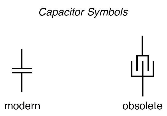
The schematic symbol is two short, parallel lines (the plates) separated by a gap. An older symbol shows interleaved plates, reflecting the actual construction of many capacitors.
When a voltage is applied, the field between the plates charges the capacitor: electrons accumulate on the negative plate, while the positive plate loses electrons. This charge separation stores energy in the electric field. The greater the voltage difference, the larger the field flux, and the more energy the capacitor can hold.
Unlike resistors, which dissipate energy as heat, capacitors store energy as a potential difference. They tend to maintain their voltage: if the voltage rises, the capacitor draws current to oppose the change; if the voltage falls, it supplies current to counter the decrease. This property is analogous to Newton’s First Law for electric charge.
In practice, real capacitors leak slowly, so their stored charge decays over time—often over years for high-quality types.
During charging, current flows from the source into the capacitor; during discharging, current flows from the capacitor into the load. The direction of electron flow relative to the voltage polarity is illustrated below.
Charging: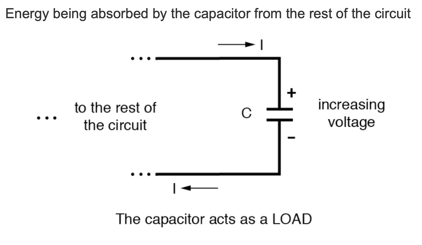
Discharging: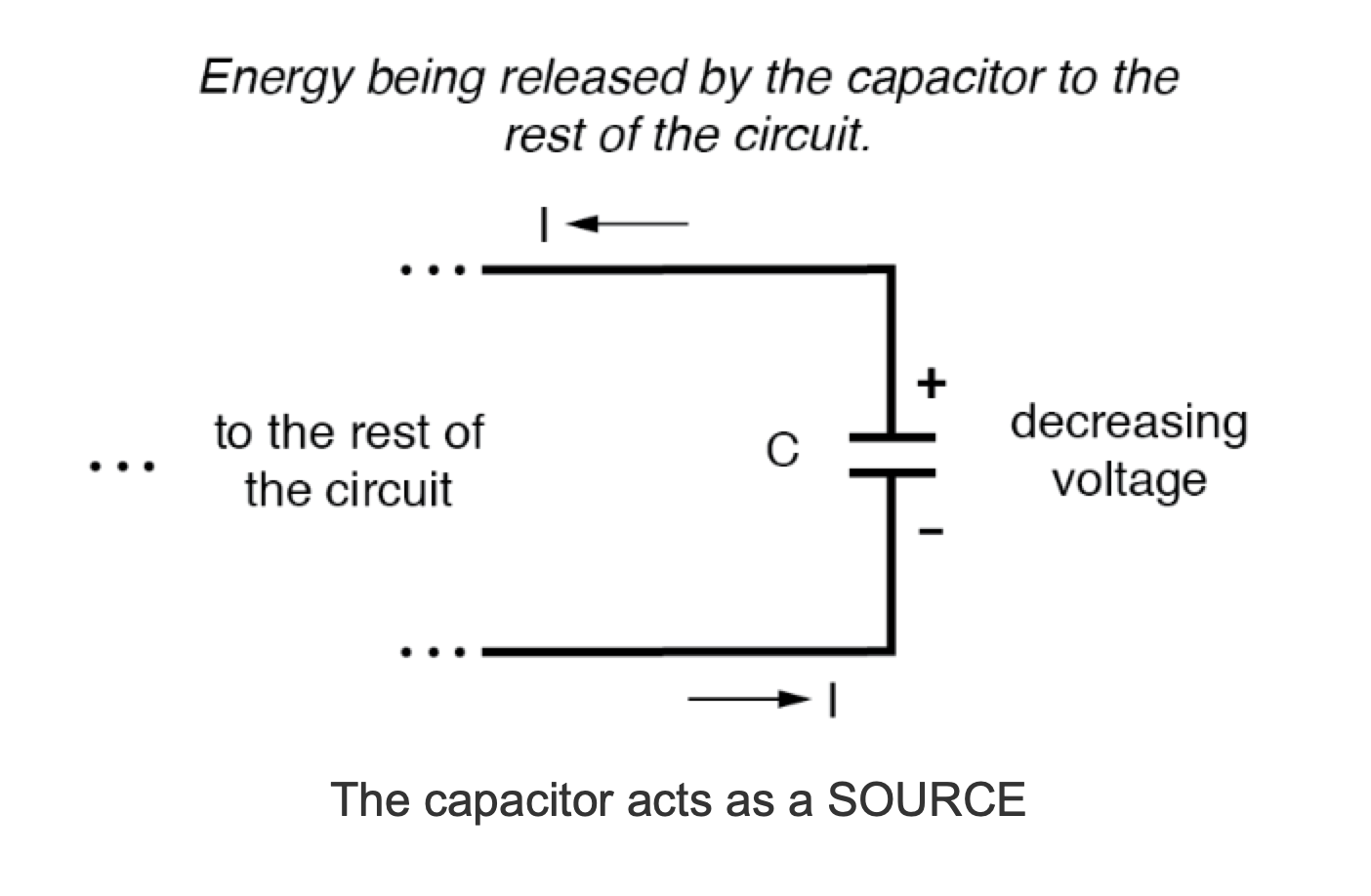
When a voltage step is applied to an uncharged capacitor, it initially draws current until its voltage matches the source. When a charged capacitor is connected to a load, it supplies current until its voltage drops to zero. In this way, capacitors can be viewed as rechargeable energy stores, similar to batteries but operating on electric fields.
Dielectric Materials and Capacitance
The dielectric—the insulating material between plates—greatly influences how much field flux, and therefore charge, can develop for a given voltage. The dielectric’s ability to permit field lines is quantified by its permittivity. Materials with higher permittivity allow greater capacitance.
Capacitance (symbol C) is the measure of a capacitor’s ability to store charge for a given voltage. It also indicates how much current will flow for a given rate of voltage change. Capacitance is measured in Farads (F). Because typical values can be very small, the metric prefix micro (µ) is often used, leading to units such as microfarads (µF). A large capacitor may be rated 330,000 µF (0.33 F). The use of micro is historical and persists in most modern specifications.
Legacy Terminology
Capacitors were historically called condensers (or condensors). The term appears mainly in older literature and in automotive contexts where a small condenser suppresses spark across ignition points.
Key Takeaways
- Capacitors resist changes in voltage by drawing or supplying current in the direction needed to oppose the change.
- When voltage increases, a capacitor acts as a load, drawing current; when voltage decreases, it acts as a source, supplying current.
- Capacitance, measured in Farads, quantifies the amount of charge a capacitor can store per volt and its opposition to voltage change.
- Dielectric permittivity determines how much field flux a capacitor can sustain for a given voltage.
- Capacitors were once commonly called condensers, though this terminology is now largely obsolete.
Industrial Technology
- Detecting AC Electric Fields: A Hands‑On Guide to Electrostatic Coupling and Shielding
- How Plate Area, Spacing, and Dielectric Material Determine Capacitance
- Understanding Magnetic Fields and Inductance: Principles, Applications, and Design
- Fundamentals of Radio: How Electromagnetic Waves Are Generated and Transmitted
- Electrical Signal Propagation at Light Speed: A 186,000‑Mile Thought Experiment
- C++ Structures vs Classes: A Practical Guide for Embedded Developers
- Tuning Electronic and Optical Anisotropy in Monolayer GaS via Vertical Electric Fields
- Advanced Magnetic Field Detection with NASA’s Fiber Bragg Grating Technology
- ergFET: NASA’s Advanced Solid‑State Sensor for Detecting Electric Fields and Characterizing Materials
- Field Service Management Explained: Why It Drives Business Success