


How Plate Area, Spacing, and Dielectric Material Determine Capacitance
Capacitance is governed by three core physical parameters of a capacitor: plate area, plate spacing, and dielectric permittivity. These factors dictate how much electric‑field flux—essentially the charge that can be stored—develops for a given voltage across the plates.
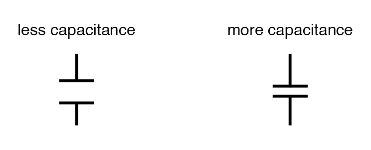
Plate Area
All else being equal, a larger plate area yields a higher capacitance, while a smaller area reduces it. This is because a larger surface can collect more charge for the same electric‑field strength.
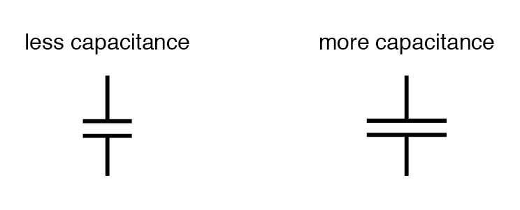
Plate Spacing
When the plates are brought closer together, the electric field intensity (voltage divided by distance) increases, which in turn raises the stored charge and thus the capacitance. Increasing the gap does the opposite.
Dielectric Material
Materials with higher relative permittivity (dielectric constant) allow a greater amount of electric‑field flux for the same applied voltage. Consequently, a capacitor using a high‑k dielectric will have a larger capacitance than one using a low‑k material under identical geometrical conditions.
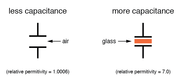
Relative permittivity is the ratio of a material’s permittivity to that of vacuum. For example, glass, with a relative permittivity of 7, permits an electric field flux seven times stronger than vacuum, all other factors being equal.
| Material | Relative Permittivity (Dielectric Constant) |
|---|---|
| Vacuum | 1.0000 |
| Air | 1.0006 |
| PTFE, FEP ("Teflon") | 2.0 |
| Polypropylene | 2.20 to 2.28 |
| ABS resin | 2.4 to 3.2 |
| Polystyrene | 2.45 to 4.0 |
| Waxed paper | 2.5 |
| Transformer oil | 2.5 to 4 |
| Hard Rubber | 2.5 to 4.80 |
| Wood (Oak) | 3.3 |
| Silicones | 3.4 to 4.3 |
| Bakelite | 3.5 to 6.0 |
| Quartz, fused | 3.8 |
| Wood (Maple) | 4.4 |
| Glass | 4.9 to 7.5 |
| Castor oil | 5.0 |
| Wood (Birch) | 5.2 |
| Mica, muscovite | 5.0 to 8.7 |
| Glass‑bonded mica | 6.3 to 9.3 |
| Porcelain, Steatite | 6.5 |
| Alumina | 8.0 to 10.0 |
| Distilled water | 80.0 |
| Barium‑strontium‑titanite | 7500 |
For a pair of conductors separated by a uniform dielectric, the capacitance can be estimated with the following formula:
Variable Capacitors
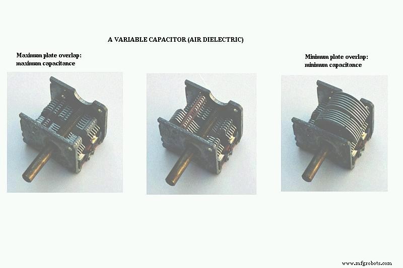
Capacitance can be made tunable by adjusting any of the above parameters. A common approach is to vary the effective plate overlap. The image below shows a typical variable capacitor that uses interleaved metal plates and an air gap. Rotating the shaft changes the overlapping area, thereby adjusting the capacitance in the picofarad range—a configuration frequently employed in radio-frequency circuits.
Related Worksheets
- Capacitors Worksheet
- Algebraic Substitution for Electric Circuits Worksheet
Industrial Technology
- Optimizing Tungsten Powder: Key Performance Drivers
- Electric Fields and Capacitors: Fundamentals, Functionality, and Design
- Key Factors Determining Inductance in Coil Design
- Essential Factors Influencing Laser Cutting Quality for Optimal Precision
- Key Factors Influencing Coke Consumption in Blast Furnace Operations
- What Drives the Cost of Anodizing Aluminum? Key Factors Explained
- Key Factors Influencing BGA Assembly Quality: A Comprehensive Guide
- Key Factors Determining Electroplating Layer Quality
- Key Factors Driving Laser Cutting Costs: What You Need to Know
- Key Factors Influencing Robotic Clamp Performance and Cost