


Key Factors Determining Inductance in Coil Design
Inductance, the ability of a coil to store magnetic energy, is governed by four fundamental design parameters. These factors dictate how much magnetic flux a given current (amp‑turns) can generate.
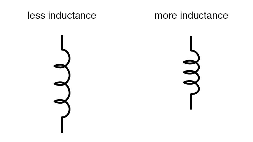
Number of Wire Turns
All else equal, increasing the number of turns boosts inductance; reducing turns diminishes it.
Why? More turns mean more amp‑turns for a fixed current, amplifying the magnetic field.
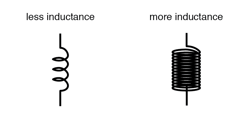
Coil Cross‑Sectional Area
A larger coil area eases the formation of magnetic flux, raising inductance; a smaller area does the opposite.
Why? Greater area reduces flux resistance for a given amp‑turns.
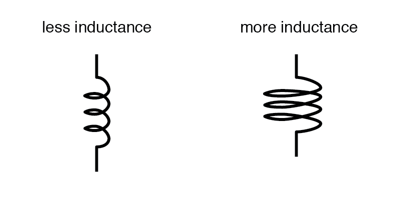
Coil Length
Shorter coils yield higher inductance, while longer coils lower it.
Why? Longer magnetic paths increase opposition to flux creation per amp‑turns.
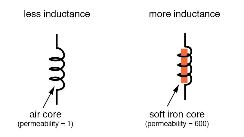
Core Material Permeability
A core with higher magnetic permeability amplifies inductance; lower permeability reduces it.
Why? Permeable materials guide magnetic flux more effectively, boosting inductance for the same amp‑turns.
An approximate inductance calculation is:
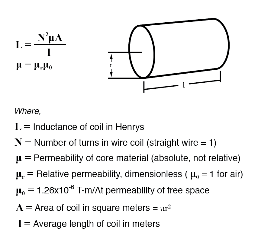
This equation provides only a rough estimate because permeability (μ) varies with magnetic field intensity (non‑linear B‑H curves). Variations in μ, core hysteresis, and saturation can cause inductance to shift as current changes.
Designers mitigate these effects by keeping flux density well below saturation, ensuring operation in the linear portion of the B/H curve.
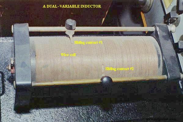
Variable inductors allow real‑time adjustment of one or more parameters—most commonly the effective number of turns (via sliding contacts) or the core position. An example of a variable air‑core inductor used in early radio receivers is shown below:
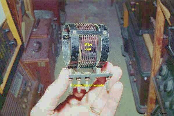
Fixed‑value inductors, often used in radio circuits, appear in the photographs below. The first is a simple air‑core design with few thick turns:
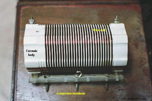
The second, with higher inductance, uses a white ceramic tube for rigidity:
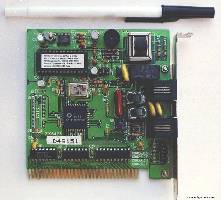
Printed‑circuit board (PCB) inductors can be remarkably small. Examine the image below and spot two inductors labeled L1 and L2, situated near R3 and C? (capacitor). These are toroidal inductors, where the coil winds around a doughnut‑shaped core.
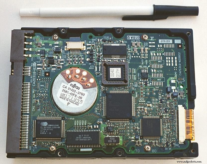
Inductors are also produced as surface‑mount devices. The photograph shows a pair of miniature inductors (L5 and L6), each marked “100”, demonstrating how small inductance values can be manufactured to meet tight design constraints.
Related Worksheets
- Inductance Worksheet
Industrial Technology
- Optimizing Tungsten Powder: Key Performance Drivers
- How Plate Area, Spacing, and Dielectric Material Determine Capacitance
- Understanding Mutual Inductance and Transformers: Principles, Applications, and Key Concepts
- Essential Factors Influencing Laser Cutting Quality for Optimal Precision
- Key Factors Influencing Coke Consumption in Blast Furnace Operations
- What Drives the Cost of Anodizing Aluminum? Key Factors Explained
- Key Factors Influencing BGA Assembly Quality: A Comprehensive Guide
- Key Factors Determining Electroplating Layer Quality
- Key Factors Driving Laser Cutting Costs: What You Need to Know
- Key Factors Influencing Robotic Clamp Performance and Cost