


Linear Hall‑Effect Position Sensing: Optimizing Linearity and Slope in Slide‑By Configurations
Linear Response in Slide‑By Hall‑Effect Sensors
Hall‑effect sensors are a proven choice for robust, maintenance‑free position detection. Because they are non‑contact, they deliver higher reliability and longer life in harsh environments.
Why Linearity Matters
In many proximity applications the exact sensor output need not be linear; a simple head‑on or slide‑by layout is sufficient. However, when you need fine positional control—such as in precision tooling or automated material handling—a linear relationship between sensor voltage and displacement dramatically improves measurement accuracy and simplifies calibration.
Achieving Linear Slide‑By Sensing
The configuration shown in Figure 1 places the sensor on the side of a single magnet. As the magnet moves along the x‑axis, the z‑component of the field through the sensor varies almost linearly around the zero‑displacement point. Figure 2 illustrates this linearity: the sensor output is negative for x < 0, zero at the center, and positive for x > 0, with the steepest slope near the origin.
For a 22 mm magnet, the linear region spans roughly –10 mm to +10 mm—just shy of the magnet’s length. This range is ample for many compact applications where precise positioning is required.
Extending the Linear Range
When a longer stroke is needed, a single magnet may be too large or expensive. One effective solution is to deploy an array of Hall sensors spaced along the expected travel path. By fusing the outputs, you can maintain a linear response across a total distance that exceeds the magnet’s size, as shown in Figure 3. For implementation guidance, see the Texas Instruments application note “Linear Position Sensing with Hall Effect Sensors”.
Using Slide‑By for Presence Detection
The same slide‑by geometry can serve as an on/off detector. By selecting an appropriate operating and release threshold on a digital Hall sensor (see Figure 4), you can define a precise reference point along the travel path. Because the magnetic flux density curve is symmetric, the sensor will trigger only once, eliminating ambiguity in many mechanical designs.
Increasing the Gradient for Higher Resolution
To sharpen the sensor’s sensitivity, you can add a second magnet so that its poles overlap the sensor’s active area. The resulting field profile, depicted in Figure 5, shows a steeper slope around the zero‑displacement point. This configuration enables finer discrimination of small displacements.
Additional variants—such as separating the two magnets by a fixed gap or adding a third magnet—allow you to tailor the slope and symmetry to your specific measurement requirements. For detailed design guidance, consult Honeywell’s Hall Effect Sensing and Applications manual.
For a full catalogue of related articles, visit our article archive.
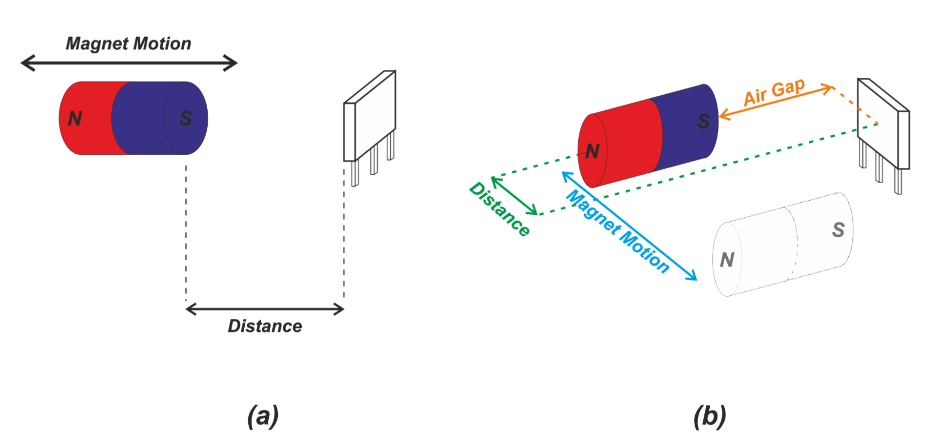
Figure 1. Head‑on vs. slide‑by sensing
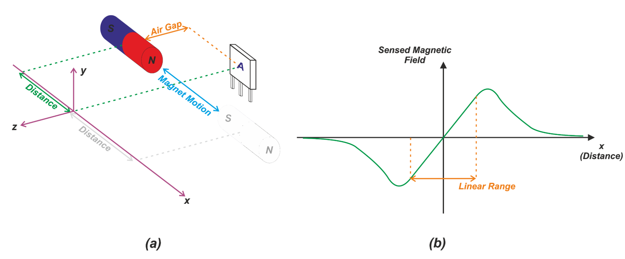
Figure 2. Linear response in slide‑by configuration
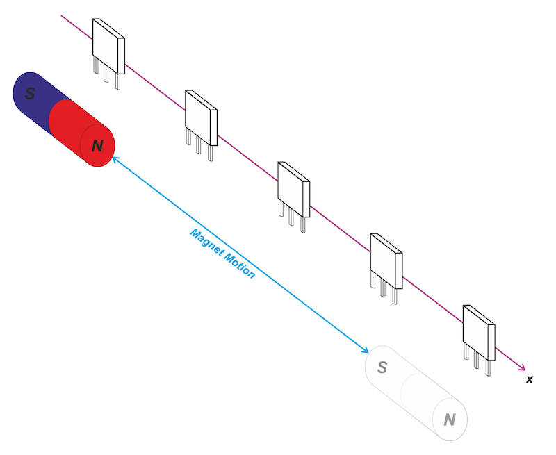
Figure 3. Array of sensors extending linear range
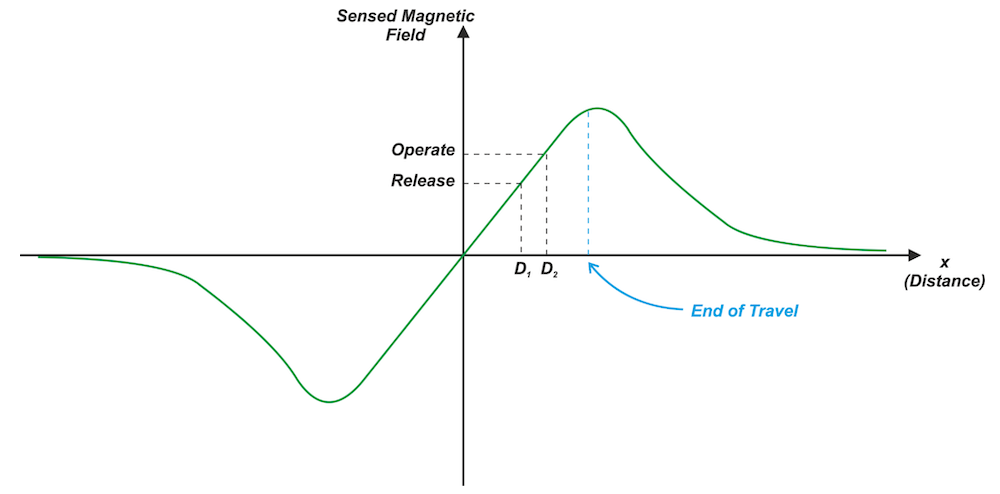
Figure 4. On/off sensor switching points
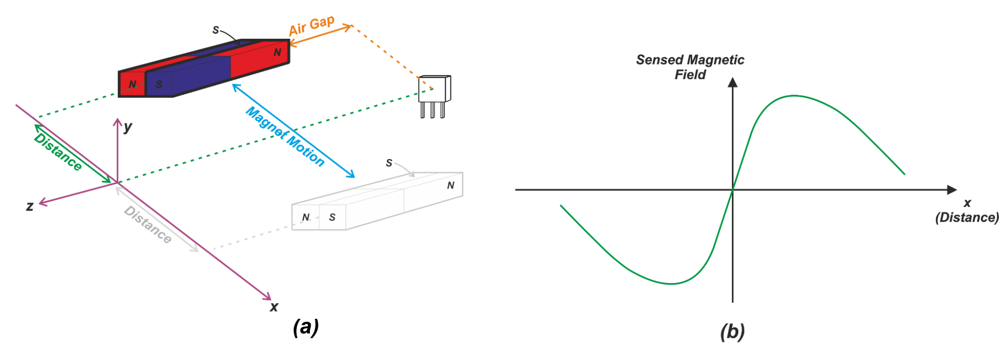
Figure 5. Steeper gradient with two‑magnet arrangement
Sensor
- Hall Effect Sensors: Working Principles & Practical Applications
- Expert Guide to Hall Effect Current Sensors: Open‑Loop & Closed‑Loop Configurations
- Digital Hall‑Effect Sensors: Unipolar, Omnipolar, Bipolar, and Latch Switches Explained
- Optimizing Hall Effect Position Sensing: Head‑On vs. Slide‑By Magnetic Configurations
- Why Control-Centric Projects Prefer Symphony Link Over LoRaWAN: Security, Reliability, and Cost Advantages
- Nanograting‑Enhanced Flexible Waveguide for Advanced Tactile Sensing
- Understanding the Hall Effect and How Hall Effect Sensors Operate
- Cambridge Researchers Develop Low-Cost, Self-Healing Sensors for Advanced Robotics
- Connecting Control Systems: Trusted Communication Interfaces for Position & Motion Sensors
- Advanced Magnetic Field Detection with NASA’s Fiber Bragg Grating Technology