


Hall Effect Sensor Pinout Explained: A Complete Reference
Have problems detected variables like the speed, displacement, or proximity of your mechanical system? Or does your project require something to detect the position of objects or the presence of a magnetic field? Well, you’re in luck because we have the answer. The Hall Effect sensor is all you need.
This sensor has a variety of uses, including identifying the polarity of a magnet pole and measuring the strength of magnetic fields.
So, in this article, we’ll tell you everything about the Hall Effect sensor and show you how to build a simple Hall Effect circuit using Arduino.
Let’s begin.
What is a Magnetic Hall Effect Sensor?
A magnetic Hall Effect sensor is a device that detects when there’s a magnetic field. Thus, when there’s a magnetic field, the output of this device will go high. On the other hand, the result would be low when there’s no magnetic field.
What’s more, you can adjust the sensitivity of the magnetic Hall Effect sensor accompanied by a potentiometer.
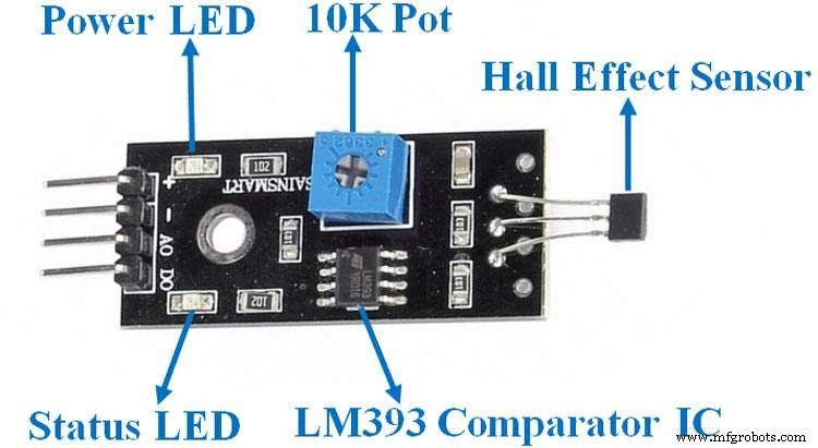
A Hall Effect module features resistors, a potentiometer, power supply, hall sensor, LED indicator, comparator LM393 IC, and capacitors.
Hall Effect Sensor Circuit
Pin Configuration
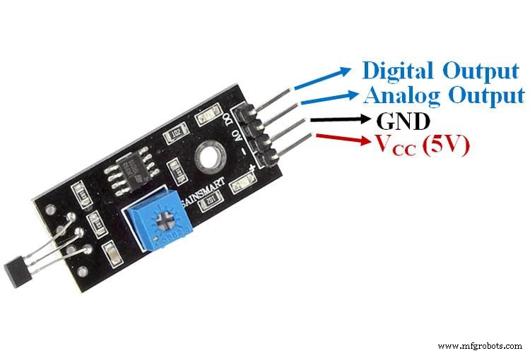
Here’s are the pin configurations for a Hall Effect sensor module:
| Pin Name | Description |
| VCC | The VCC is responsible for powering the module with +5V. |
| GND | The GND pin is the ground power supply. |
| DO | The digital output pin connects directly to the microcontroller’s digital pin. |
| AO | The analog output pin connects directly to the microcontroller’s analog pin. |
Hall Effect Sensor Pinout
Specifications
Here are the features and specifications of the magnetic hall sensor:
- It has an operating voltage of 5V DC
- The PCB size is 32x12mm
- It’s readily available, not expensive, and small
- It uses an allegro A3144 Hall-effect switch sensor
- It also uses a magnetic sensing hall effect detector type
- Features an LM393 comparator with a preset threshold
- It has a 7mm detection range
- You can easily use this sensor with any normal analog or digital integrated circuits or microcontrollers.
Working Principle
All A3114 Hall Effect sensors have materials with magnetic fields but without active charges. So, these charges will become active whenever it receives the voltage directly on the input pins.
Additionally, these charged particles create a force when they move through the magnetic field, reflecting them on a straight path.
These particles are current-carrying conductors. Thus, the whole process forms two planes. In essence, the first has the magnetic field, while the second with the current-carrying conductors or deflected charged particles.
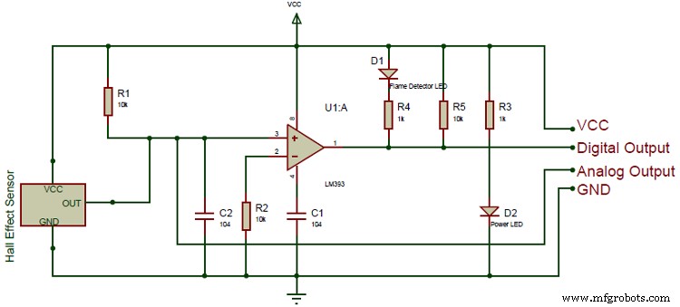
Hall Sensor Circuit Diagram
Furthermore, it results in the first plane having positive charges and the second having negative charges. Now, the voltages present between both aircraft are the Hall Effect voltages. Thus, when the force is the same between the magnetic field and charged particles, there will be no separation between the two planes.
In other words, if you don’t see any current change, the hall voltages will measure the shift or flux density of the magnetic field.
Alternative Digital Hall-Effect Sensors
Here are some alternative digital hall-effect sensors in case you can’t find the A3114 hall sensor module or want something different:
- Flex sensor
- Heart rate pulse sensor
- Infrared obstacles avoidance sensor
- Soil moisture sensor
- Flame sensor
- Shock sensor module
- Color sensor
- Rain detector
Other Analog Hall-Effect Sensors
Also, here are some other analog hall-effect sensors:
- APDS9960
- PT100 RTD
- TLE4999I3
- BH1750
- DHT22
- LM35
- VL53L0X
- CCS811
- BMP280
- HC-SR505
- MQ137
- TMP36
- BMP180
- ADXL335
- DHT11
- MPX4115A
- MPU6050
How to Interface A3144 Hall Effect Sensor Accompanied by Arduino Board
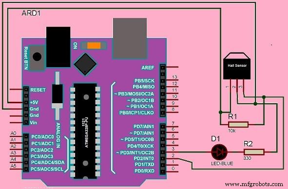
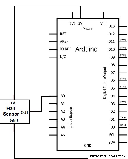
You’ll need a controller if you’re going to check magnetic flux density via a Hall Effect sensor. So, in this case, we’ll be using an Arduino board. Thus, you can interface your A2144 Hall Effect sensor accompanied by an Arduino board via the wiring connections shown in the circuit diagram below:
Arduino Wiring Connections
The circuit diagram shows that the Arduino powers up the Hall Effect sensor, and a single LED connects to the Arduino’s output. The LED serves as an indicator. Thus, when the circuit detects the existence of a magnetic field, it turns on the LED.
When you make the necessary connections, you’ll write a straightforward logic program using the Arduino library and then upload the code through the Arduino IDE software to the Arduino board.
Furthermore, put on your Arduino board and bring a magnet close to this circuit to check if your interface worked. The Hall Effect sensor should detect the appeal and send a high logic signal to the Arduino board if it works. The Arduino should then turn the LED.
Hall Effect Sensor Pinout– How to Build a Hall Effect Sensor Circuit
For this circuit, we will use the Allegro A1302 Hall Effect sensor to detect magnetic fields. Then, we’ll connect the sensor to an Arduino board to read the voltage from the A1302’s output and display it on a screen.
So, if you place a magnet close to the sensor, there will be a change in readings. This means the sensor detects the magnet close.
Required Components
- Hall effect sensor (A1302) (1)
- Arduino Uno board (1)
- USB (1)
Note: the pinout of the A1302 Hall Effect is different from the sensor previously mentioned. Rather than four pinouts, this IC has only three (VIN, GND, and VOUT). Pin 1 takes in positive DC voltage for the operation of the IC (4.4-6V), while Pin 2 is the ground pin. It means it takes in the negative terminal of the DC power supply. Lastly, Pin 3 is the output pin. It releases an analog voltage depending on the density of the magnetic field.
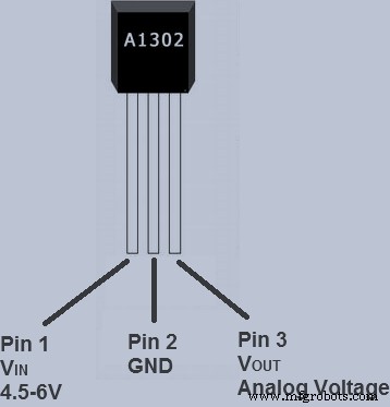
A1302 Pinout
Hall Effect Sensor Pinout– Circuit Diagram
Here is the circuit diagram and schematic:
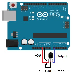
Circuit Diagram
Circuit Schematic
Hall Effect Sensor Pinout– Steps
Follow the above schematic to connect your Hall Effect sensor to your Arduino board to build this circuit.
When you’re done with the connections, take your USB, connect the Arduino to your computer, and input the following code to display the magnetic field readings from your Hall Effect Sensor.
Note: the USB cable should be a Type A on one side and Type B on the other side.
//initializes/defines pin connections
int outputpin= 0;
//sets ground pin to LOW and input pin to HIGH
void setup()
{
Serial.begin(9600);
}
//main loop- Reads the raw value from the output pin and prints it out
void loop()
{
int rawvalue= analogRead(outputpin);
Serial.println(rawvalue);
delay(5000);
}
Though the device doesn’t have the best sensitivity, it will show a change in readings when you place a magnet close to it.
Hall Effect Sensor Pinout–Applications
You can use the Hall Effect sensor circuit for the following applications:
- Pulse counting
- Door open/close detection
- Valve positioning
- Docking detection
- Proximity sensing

Wrapping Up
Interfacing an Arduino with Hall Effect sensors is one of the most effective ways of reading magnetic fields. Why? Because most sensors operate with a 4.5-6V input, and an Arduino supplies 5V power, thus making it perfect for the sensor.
Also, you can define your pin connections with the Arduino code and read the analog voltage from your sensor’s output pin. Here’s the best part. The Arduino only reads the raw value without computations or conversions—and displays it.
Well, that brings this article to an end. Have any questions? Feel free to reach us here. And we’ll be happy to help.
Industrial Technology
- Your Definitive Guide to 3D Printing: From Basics to Advanced Techniques
- Mastering Inventory Management: Proven Strategies for Every Business
- Comprehensive Guide to LM317 Pinout and Voltage Regulation
- USB Pinout Explained: A Comprehensive Beginner’s Guide
- Mastering Ultrasonic Sensor Circuits: The Ultimate Guide
- DPDT Relays Explained: Complete Wiring & Applications Guide
- LM386 Audio Amplifier IC: In-Depth Guide & Practical Uses
- STM32 Pinout Guide: Mastering Microcontroller Connections
- YF-S201 Hall Effect Water Flow Sensor: Pinout, Features & Practical Applications
- Mastering Hall Effect Sensors: Principles, Applications, and Design