


Optimizing Power Systems: Parallel Operation of Single‑Phase and Three‑Phase Transformers
Needs & Conditions for Parallel Connection of Transformers
In a power system network, transformers are used to step up and step-down voltage levels. The rating of a transformer is selected according to the load demand. But load demand increases day by day. Hence, to meet extra load demand, we need to change the existing transformer to a higher capacity transformer or we can add an extra transformer connected with the existing transformer.
- Related Post: Parallel Operation of DC Generators
The economic way to meet load demand is to connect a second transformer in parallel with the existing transformer.
Need of Parallel Operation of Transformers
The parallel operation of the transformer is needed due to following reasons.
- To supply a load of more ratings to the existing transformer, we need to connect the second transformer in parallel with the existing transformer.
- At the time of maintenance, a second transformer is used to maintain continuity of supply to the consumer. It increases the reliability of a system.
- When one transformer is in fault condition or fails to operate due to any reason, the second transformer is used to supply and avoid intrusion of power.
Conditions for Parallel Operation of Transformers
To ensure the successful parallel operation of the transformers, the following conditions must be satisfying.
- The primary winding of both transformers is suitably designed for the supply system voltage and frequency.
- Both transformers are connected with the same polarity. If polarities are not matched there is a chance of short-circuiting. Hence, while connecting both transformers in parallel, the polarity of both transformers must match.
- The turns ratio (transformation ratio) of both transformers should be identical. It means the voltage rating of primary and secondary windings should be identical. If the turns ratio is not the same, the parallel operation of transformers is possible. But some amount of circulating current will flow in no-load conditions. And it will create unequal loading conditions.
- In order to avoid circulating current, the X/R ratio must be the same. It means the impedance triangle must be identical for both transformers. If the X/R ratio is not the same, both transformers will operate on different power factors.
- When both transformers have different KVA ratings, the equivalent impedance is inversely proportional to the individual kVA rating (circulating current is ignored).
Parallel Operation of Single-Phase Transformer
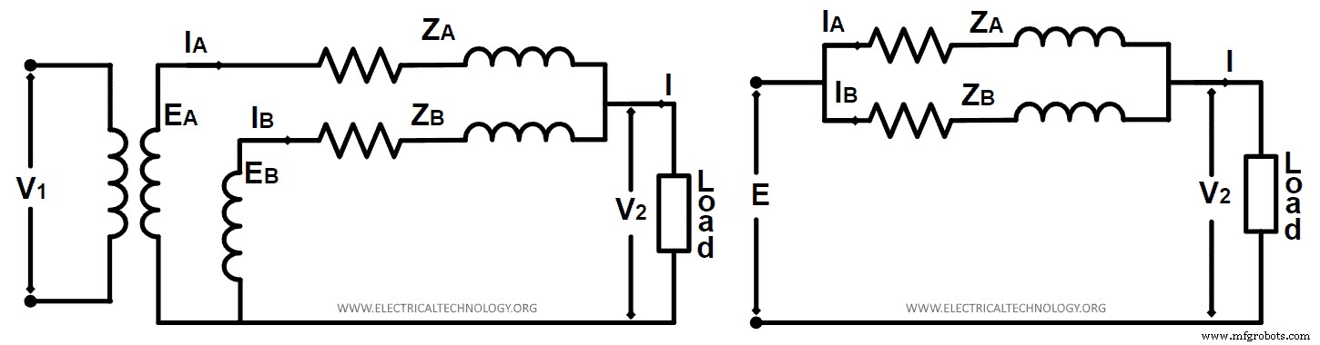
Two single-phase transformers can be connected in parallel as shown in the figure below.
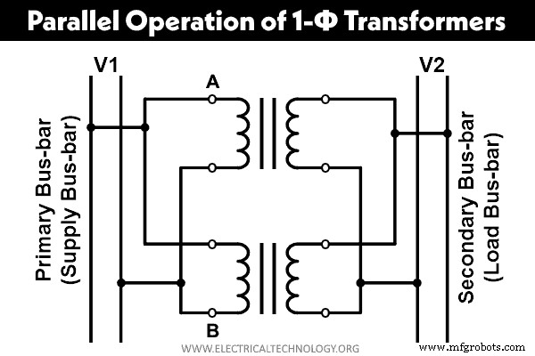
As shown in the figure, the primary winding of both transformers is connected with the supply bus bar and the secondary winding of both transformers is connected with the load bus bar. In this way, we can connect two or more than two transformers in parallel and exceed transformer ratings.
While connecting transformers in parallel, the polarities of the transformer must be matched. Otherwise, it will lead to short-circuit and may damage the transformer.
Ideal Condition
In an ideal condition, we consider both transformers have the same voltage ratio and same turns ratio. So, the impedance triangle of both transformers is identical in shape and size. The phasor diagram of this condition is as shown in the figure below.
Where,
- E = No-load secondary voltage of each transformer
- V2 = Secondary (load) terminal voltage
- V1 = Primary (supply) terminal voltage
- IA = Current supplied by transformer-1
- IB = Current supplied by transformer-2
- I = Total current
As shown in the phasor diagram, the total load current (I) is legging behind V2 by an angle of ф. And current IA and IB of an individual transformer are in phase with total current (I).
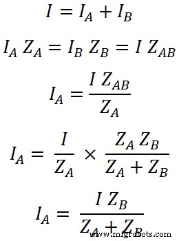
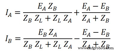
And individual current (IA and IB) for each transformer is;
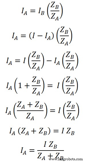
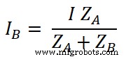
Similarly, current IB is derived as;
Equal Voltage Ratios
Let’s assume that, the transformers have the same voltage ratio. Hence, no-load voltage of both transformers is equal (EA = EB = E). In this condition, no current will flow between two transformers. The equivalent circuit of this condition is as shown in the figure below.
Where,
- EA, EB = No-load voltage
- ZA, ZB = Impedances
- IA, IB = Secondary current of respective transformer
- V2 = Terminal voltage
- I = Total current
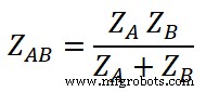
Here, the impedance of both transformers is connected in parallel. Hence, total impedance ZAB is;
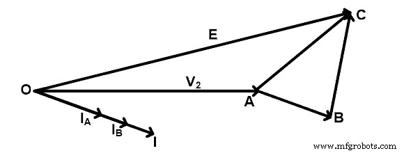
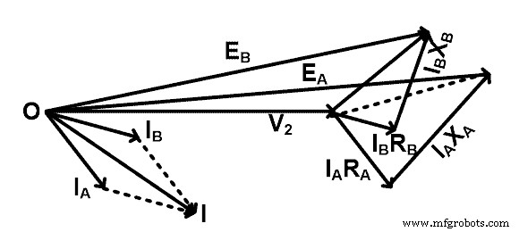
Vector diagram of this condition is as shown in the figure below.

Here, current IA and IB are not in phase. Hence, the total current supplied to the load is a phasor summation of IA and IB. And total current (I) is as shown in the vector diagram. Here, we have considered that the no-load voltage of each transformer is the same and it is in-phase in the vector diagram.
Similarly,
Let’s assume QA and QB are power consumed by each transformer respectively.
QA = V2 IA and QB = V2 IB
The total power consumed by both transformers is Q;
Q = V2 I
Now,
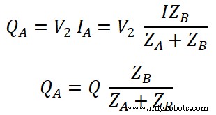
Similarly,
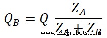
Therefore, QA and QB are obtained in magnitude and in-phase from the above vectorial equations.
Unequal Voltage Ratio
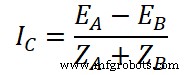
If the transformation ratio is not the same for both transformers, no-load secondary voltage is not the same. In this condition, some amount of current will flow between transformers in no-load conditions. This current is known as circulating current IC.
Vector diagram of this condition is as shown in the figure below.
The no-load EMF of both transformers is not the same in this condition. Hence,
EA = IA ZA + I ZL
EB = IB ZB + I ZL
Where,
ZL = load impedance
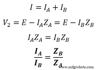
I = IA + IB and V2 = I ZL
So,
EA = IA ZA + (IA + IB) ZL
EB = IB ZB + (IA + IB) ZL
Subtract the above equations;
EA – EB = IA ZA – IB ZB
(EA – EB) + IB ZB = IA ZA
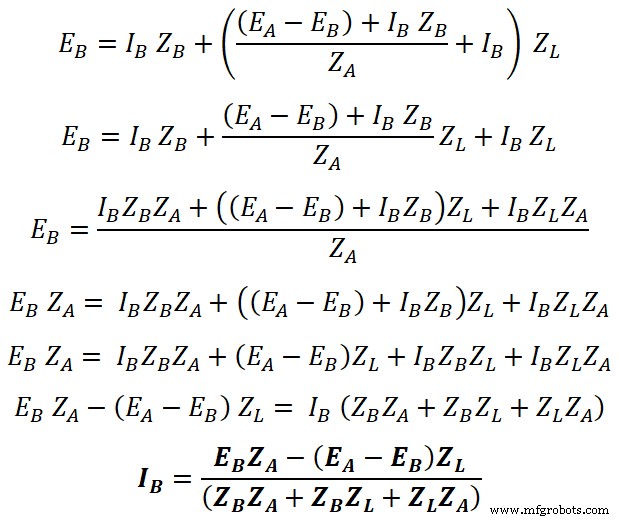
Put the value of IA in the equation of EB;
Similarly,
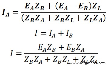
Now, put the value of total current (I) in the equation of terminal voltage V2;
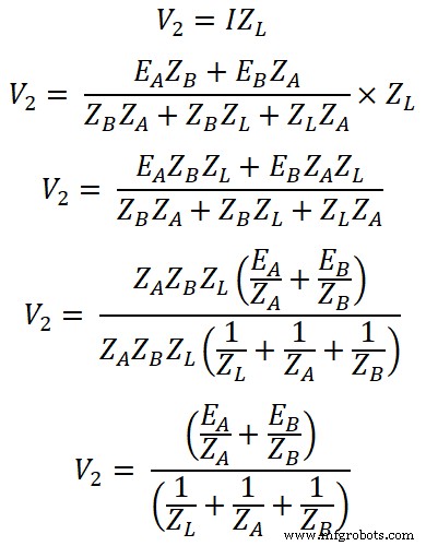
The transformer impedances (ZA and ZB) are always smaller than the load impedance ZL. So, to make the equation easy, we neglect ZA ZB in comparison with ZL (ZA+ZB).
Parallel Operation of Three-Phase Transformers
In a three-phase transformer also, we can connect two or more than two transformers in parallel to increase load capacity. The conditions required in the parallel operation of a three-phase transformer are the same as a single-phase transformer. Additionally, there is some condition that must be followed.
- The phase sequence of both transformers is the same and it is verified by the phase sequence indicator.
- Phase displacement between the primary winding and secondary winding must be the same.
- All three transformers used in the transformer bank must be the same type of transformer (Core or shell).
- While calculating voltage ratio, consider line voltages. And keep the voltage ratio the same.
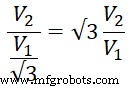
The There should be a voltage ratio between the primary and secondary terminal voltage. It shows this voltage ratio is not equal to the ratio of number of turns per phase. For example, if V1 and V2 are the primary and secondary terminal voltage respectively, then the turn ratio for Star / Delta connection (Y-Δ) would be:

The circuit diagram of the parallel operation of a three-phase transformer is as shown in the figure below.
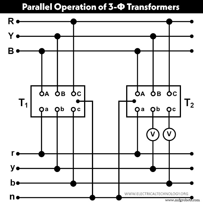
The primary and secondary winding of both transformers (T1 and T2) are connected as shown in the above figure. Here, the b and c terminals of the secondary winding are kept flexible and connected with a voltmeter for testing purposes. If both voltmeters show zero reading, the polarities are correct. If the voltmeter shows twice of phase voltages, the polarities are wrong.
Related Posts:
- Transformer Phasing: The Dot Notation and Dot Convention
- Transformers Fire Protection System – Causes, Types & Requirements
- Current Transformers (CT) – Types, Characteristic & Applications
- Autotransformer – Its Types, Operation, Advantages and Applications
- What is Potential Transformer (PT)? Types & Working of Voltage Transformers
- Power Transformer Protection and Faults
- Transformer Performance & Electrical Parameters
- Transformers Insulation Materials in Oil-Immersed & Dry Type T/F
- Application of Transformer
- Transformer Losses – Types of Energy Losses in a Transformer
- EMF Equation of a Transformer
- Open Delta Connections of Transformers
- Transformer Formulas and Equations
- Electrical Transformer Symbols – Single Line Transformer Symbols
Industrial Technology
- Step‑Up and Step‑Down Transformers Explained: Voltage, Current, and Power Distribution
- Three-Phase Transformer Circuits: Design, Wiring, and Practical Applications
- Four Key Tests to Evaluate Power Transformer Efficiency
- Electrical Transformers Explained: Function, Design, and Industrial Applications
- Expert Power Transformer Maintenance, Diagnostics & Monitoring – Extend Lifespan
- Comprehensive Guide to Transformer Fire Protection: Causes, Types, and Requirements
- Running a Three‑Phase Induction Motor from a Single‑Phase Power Supply: Proven Methods and Tips
- Synchronizing DC Generators: Best Practices for Parallel Operation and Load Sharing
- Single-Phase vs Three-Phase Power: Key Differences Explained
- Center‑Tapped Transformers Explained: How They Work and Where They’re Used