


Master Inductor Color Codes: Quick Guide to Decode Inductance Values
How to know the Value of Inductance of an Inductor using Standard & Color Codes – Calculators & Examples
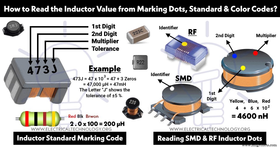
Reading Value of Inductor Marking Codes
For small Inductors like air-core, iron-core, ferrite-core or SMD inductors etc., the surface area of the component is very small hence it is not possible to print the exact value of inductance and other parameters (nameplate rating) on it. This way, some special notations and marking are used e.g. color bands, color dots, digits, numbers and alphanumeric characters which known as inductor color codes and they are used to indicates the different characteristics and values of inductance of inductors. Generally, the values of these indictors are in μH (Microhenries 1 x 10⁻⁶).
Let see how to read the value of inductors by using the standard marking codes?
2 Numerical Values:
If an inductor has two numerical values, or any two digits and a letter like 11N, it means the value is 11 nH (nanohenry).
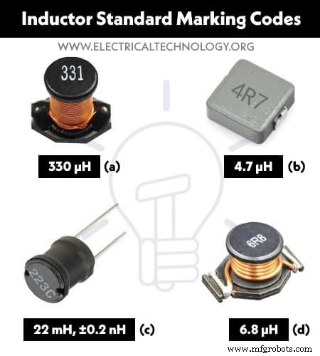
- If there is a letter (mostly R which shows dot “.”) in the middle of two digits like 6R8, it shows:
For example: 6R8 = 6.8 μH.
- If the first or middle letter is “μ”, “p” or “n” instead of R, it represents the main units of Inductance such as
For examples:
- 5μ = 5 Micro-henry
- 3μ1 = 3.1 Micro-henry
- N42 = 42 Nano-henry
3 Numerical Values:
Most of the inductors have three numerical values printed on it. For example, 220, 221, 222, 223, 331, 332 etc. Let’s see how to read these values. Suppose the printed value on an inductor is “332”
- 332 = 33 x 102 = 3300 μH (Microhenry)
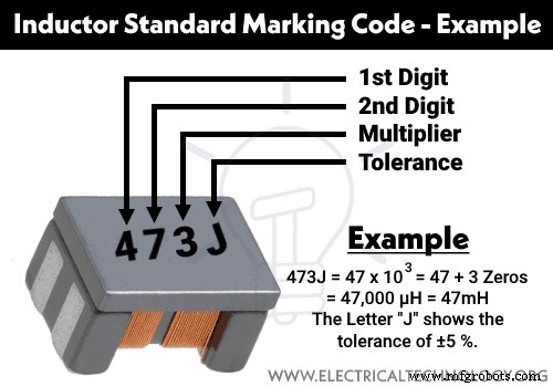
Similarly, if the specials marking code on the inductor is 223J: (3 Digits + 1 Alphabet), the fourth one character (“J” in this case) shows the tolerance of the inductor: For example:
- 223J = 22 x 103 = 22 + 3 Zeros = 22,000 µH = 22mH
- The Letter “J” shows a tolerance of ±5 %.
- Hence the value of inductance is = 22mH, ±5 %
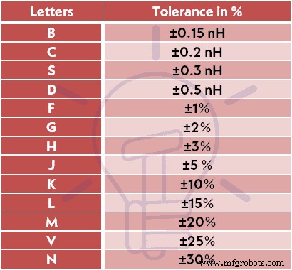
Tolerance of Inductors
There are Capital letters printed on the inductors except the value of inductance such as 223J.
The following table shows the tolerance for inductors indicated by Letters.
| Letters | Tolerance in % |
| B | ±0.15 nH |
| C | ±0.2 nH |
| S | ±0.3 nH |
| D | ±0.5 nH |
| F | ±1% |
| G | ±2% |
| H | ±3% |
| J | ±5 % |
| K | ±10% |
| L | ±15% |
| M | ±20% |
| V | ±25% |
| N | ±30% |
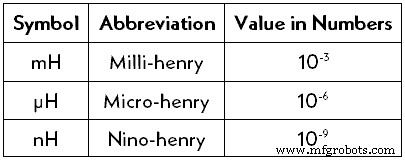
The following symbols and units are used to represent the values of inductance of indictor in Millihenries (mH), Microhenries (μH) & Nanohenries (nH).
| Symbol | Abbreviation | Value in Numbers |
| mH | Milli-henry | 10-3 |
| μH | Micro-henry | 10-6 |
| nH | Nino-henry | 10-9 |
Related Posts
- Series Inductors Calculator
- Parallel Inductors Calculator
Inductor Color Codes
Apart from the text marking on inductors, there are special inductor color codes namely “EIA” (Electronic Industries Association) and “Mil-Spec” (Military Specification). There are three, four or five color bands printed on the inductor which shows the inductance of the inductor and tolerance. Let’s see how to read 2, 3 and 4 bands color codes inductor as follows:
Reading 3 bands Inductor Color Codes
If there are three color bands marked on an inductor, it means
- 1st Color Band = First Number of Value of Inductor.
- 2nd Color Band = Second Number of value of Inductor.
- 33rd Color Band = The number of Zeros (as multiplier) with the first two digits of inductor (In numbers).
Example:
The Three color bands inductor as Red, Brown & Gold:
Red = 2, Brown = 1 & Gold = 0.1 i.e.
- = 21 x 0.1 = 2.1 µH
Mostly, the three color band inductors have a tolerance of ±20%. This way, the value of the inductor is 2.1 µH – ±20%.
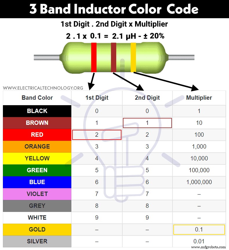
The following table shows the three bands inductor color codes and its values.
| Band Color | 1st Digit | 2nd Digit | Multiplier |
| BLACK | 0 | 0 | 1 |
| BROWN | 1 | 1 | 10 |
| RED | 2 | 2 | 100 |
| ORANGE | 3 | 3 | 1,000 |
| YELLOW | 4 | 4 | 10,000 |
| GREEN | 5 | 5 | 100,000 |
| BLUE | 6 | 6 | 1,000,000 |
| VIOLET | 7 | 7 | – |
| GREY | 8 | 8 | – |
| WHITE | 9 | 9 | – |
| GOLD | – | – | 0.1 |
| SILVER | – | – | 0.01 |
3-Bands Inductor Color Code Calculator
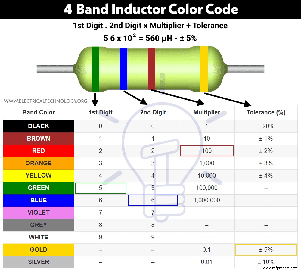
Reading 4 Bands Inductor Color Codes
If there are four color bands printed on an inductor, it means
- 1st Color Band = First Number of Value of Inductor.
- 2nd Color Band = Second Number of value of Inductor.
- 33rd Color Band = The number of Zeros (as multiplier) with the first two digits of Inductor (In numbers).
- 4th Color Band = Tolerance in percentage.
Example:
The Four color bands inductor as Green, Blue, Brown & Gold:
Green = 5, Blue = 6, Brown = 100 & Gold = ±5% i.e.
- = 56 x 102 = 560 µH
The fourth band as Golden color shows the tolerance of ±5%. Therefore, the value of the inductor is 560 µH – ±5%.
The following table shows the four bands inductor color codes and its values.
| Band Color | 1st Digit | 2nd Digit | Multiplier | Tolerance (%) |
| BLACK | 0 | 0 | 1 | ± 20% |
| BROWN | 1 | 1 | 10 | ± 1% |
| RED | 2 | 2 | 100 | ± 2% |
| ORANGE | 3 | 3 | 1,000 | ± 3% |
| YELLOW | 4 | 4 | 10,000 | ± 4% |
| GREEN | 5 | 5 | 100,000 | – |
| BLUE | 6 | 6 | 1,000,000 | – |
| VIOLET | 7 | 7 | – | – |
| GREY | 8 | 8 | – | – |
| WHITE | 9 | 9 | – | – |
| GOLD | – | – | 0.1 | ± 5% |
| SILVER | – | – | 0.01 | ± 10% |
4-Bands Inductor Color Code Calculator
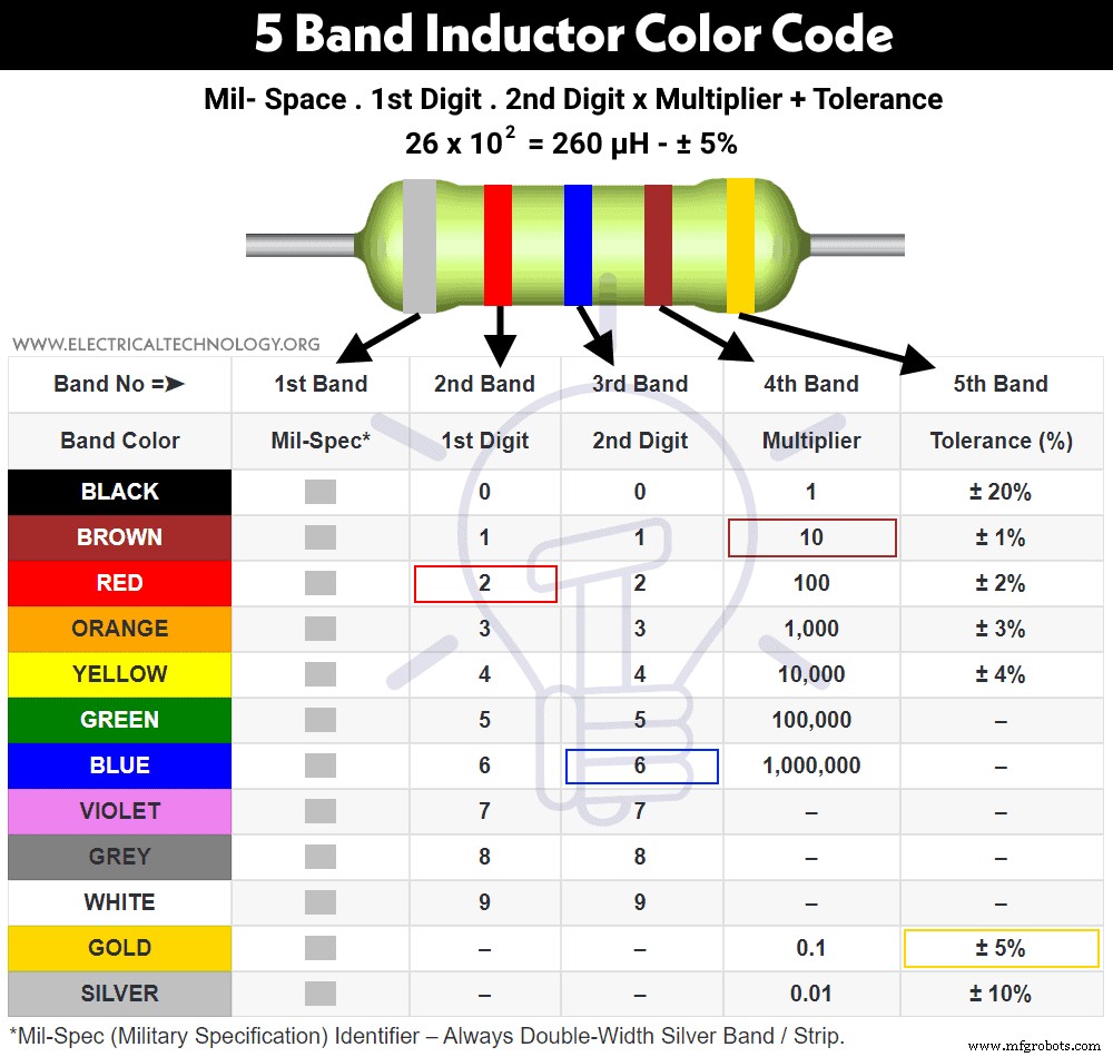
Reading 5 Bands Inductor Color Codes
If there are five color bands printed on an cylindrical molded inductor, it means
- 1st Color Band = Mil-Spec (Military Specification) Identifier – Always Double-Width Silver Band / Strip which identifies the military radio-frequency inductors.
- 2nd Color Band = First Number of Value of Inductor.
- 33rd Color Band = Second Number of value of Inductor.
- 4th Color Band = The number of Zeros (as multiplier) with the first two digits of Inductor (In numbers).
- 5th Color Band = Tolerance in percentage.
Example:
The Five color bands inductor as Silver , Red, Blue, Brown & Gold:
Silver = Mil-Spec, Red = 2, Blue = 6, Brown = 10, & Gold = ±5% i.e.
- = 26 x 10 = 260 µH
The fifth band as Golden color shows the tolerance of ±5%. Therefore, the value of the inductor is 260 µH – ±5%.
The following table shows the four bands inductor color codes and its values.
| Band No =➤ | 1st Band | 2nd Band | 3rd Band | 4th Band | 5th Band |
| Band Color | Mil-Spec*1 | 1st Digit | 2nd Digit | Multiplier | Tolerance (%) |
| BLACK | 0 | 0 | 1 | ± 20% | |
| BROWN | 1 | 1 | 10 | ± 1% | |
| RED | 2 | 2 | 100 | ± 2% | |
| ORANGE | 3 | 3 | 1,000 | ± 3% | |
| YELLOW | 4 | 4 | 10,000 | ± 4% | |
| GREEN | 5 | 5 | 100,000 | – | |
| BLUE | 6 | 6 | 1,000,000 | – | |
| VIOLET | 7 | 7 | – | – | |
| GREY | 8 | 8 | – | – | |
| WHITE | 9 | 9 | – | – | |
| GOLD | . *2 | . *2 | 0.1 | ± 5% | |
| SILVER | – | – | 0.01 | ± 10% |
- *1 Mil-Spec (Military Specification) Identifier – Always Double-Width Silver Band / Strip.
- *2 Decimal Points (.) instead of significant figures.
5-Bands Inductor Color Code Calculator
Inductance Value Code to Inductor Color Codes Calculator
The following calculator will convert the value of inductance printed in code on an inductor to the four bands of inductor color codes. This calculator supports 4-colored strips and values of inductances in H (Henries), mH (milli-henries) and µH (micro-henries). Just put the code of the inductor in digits e.g. 100, 102, 233 etc and click on calculate for the desired color codes.
Reading Chip & SMD (Surface Mount Device) Inductor Color Codes
On SMD inductors, there is no possibility to print the inducting marking or color code bands due to the small surface area of the tiny component. This way, only colored dots are printed on these inductors to represent the value of inductance in nanohenries. Keep in mind that these dots do not represent the polarity of the inductors and can only be used in clockwise direction to determine the value of SMD inductors.
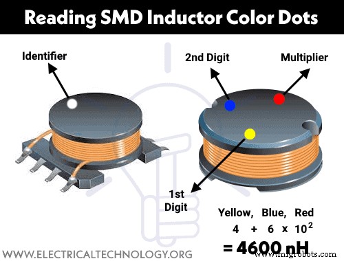
For Example:
The colored dots in clockwise direction on an SMD inductor are Yellow, Blue & Red. This way:
- Yellow = 4
- Blue = 6
- Red = 102
Hence the value of the SMD inductor is 4600 nH.
Reading RF (Radio Frequency) Inductor Color Dots Codes
Radio frequency or RF inductors are the same like SMD and chip inductors in size. The marking method is the same as the above one i.e. if there is only one color dot, it shows the inductance and other specifications can be seen in the related datasheet.
On the other hand, if there are three colored dots printed on the RF inductors, the first two opposite colored dots (in clockwise direction) show the first and second digit (significant figures) respectively while the single dot on the other end represents the multiplier.
Good to know: The single or three dots are not supposed to represent the polarity of the inductor but only the value of inductance in nanohenries (nH).
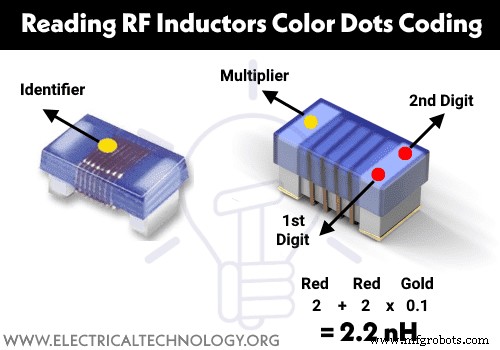
For Example:
The colored dots in clockwise direction on an RF inductor are RED, RED & Gold. This way:
- Red = 2
- Red = 2
- Gold = 0.1
Hence the value of the RF inductor is 2.2 nH.
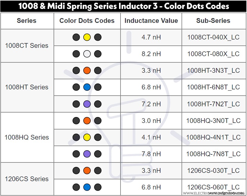
The following table shows the 1008 and Midi Spring Series Inductor 3 – Color Dots Codes and its values of inductances in nH.
| Series | Color Dots Codes | Inductance Value | Sub-Series |
| 1008CT Series | ⚫ 🟡 ⚫ | 4.7 nH | 1008CT-040X_LC |
| ⚫ ⚪ ⚫ | 8.2 nH | 1008CT-080X_LC | |
| 1008HT Series | ⚫ 🟠 ⚫ | 3.3 nH | 1008HT-3N3T_LC |
| ⚫ 🔵 ⚫ | 6.8 nH | 1008HT-6N8T_LC | |
| ⚫ 🟣 ⚫ | 7.2 nH | 1008HT-7N2T_LC | |
| 1008HQ Series | ⚫ 🟠 ⚫ | 3.0 nH | 1008HQ-3N0T_LC |
| ⚫ 🟡 ⚫ | 4.1 nH | 1008HQ-4N1T_LC | |
| ⚫ 🟣 ⚫ | 7.8 nH | 1008HQ-7N8T_LC | |
| 1206CS Series | ⚫ 🟠 ⚫ | 3.3 nH | 1206CS-030T_LC |
| ⚫ 🔵 ⚫ | 6.8 nH | 1206CS-060T_LC |
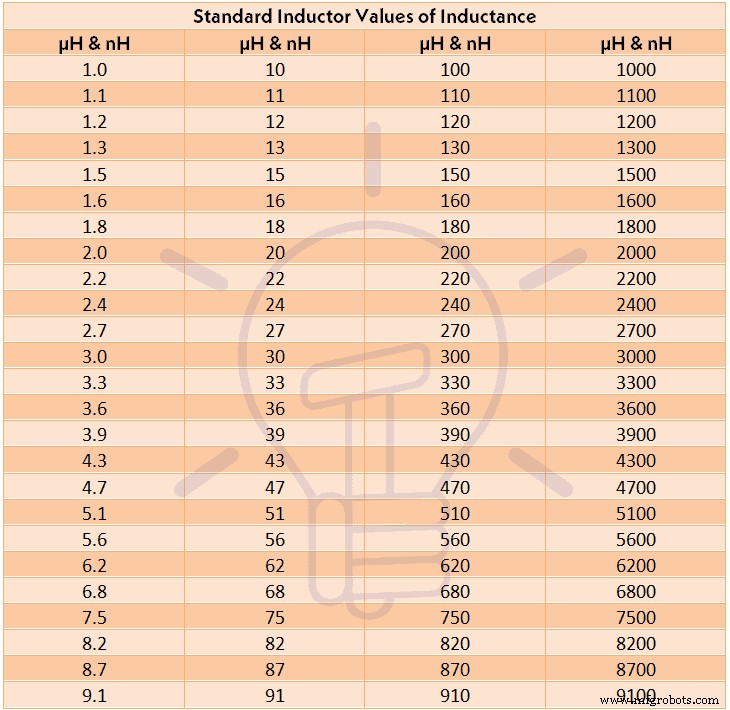
Standard Inductor Values of Inductance
Following is the table of most common used and available inductors both in µH (microhenries) and nH (nanohenries).
| Standard Inductor Values of Inductance | |||
| µH & nH | µH & nH | µH & nH | µH & nH |
| 1.0 | 10 | 100 | 1000 |
| 1.1 | 11 | 110 | 1100 |
| 1.2 | 12 | 120 | 1200 |
| 1.3 | 13 | 130 | 1300 |
| 1.5 | 15 | 150 | 1500 |
| 1.6 | 16 | 160 | 1600 |
| 1.8 | 18 | 180 | 1800 |
| 2.0 | 20 | 200 | 2000 |
| 2.2 | 22 | 220 | 2200 |
| 2.4 | 24 | 240 | 2400 |
| 2.7 | 27 | 270 | 2700 |
| 3.0 | 30 | 300 | 3000 |
| 3.3 | 33 | 330 | 3300 |
| 3.6 | 36 | 360 | 3600 |
| 3.9 | 39 | 390 | 3900 |
| 4.3 | 43 | 430 | 4300 |
| 4.7 | 47 | 470 | 4700 |
| 5.1 | 51 | 510 | 5100 |
| 5.6 | 56 | 560 | 5600 |
| 6.2 | 62 | 620 | 6200 |
| 6.8 | 68 | 680 | 6800 |
| 7.5 | 75 | 750 | 7500 |
| 8.2 | 82 | 820 | 8200 |
| 8.7 | 87 | 870 | 8700 |
| 9.1 | 91 | 910 | 9100 |
Charts & Tables in image format:
Industrial Technology
- Resistor Color Codes – A Comprehensive Guide to Decoding Value, Tolerance, and E-Series Standards
- Standard Wiring Color Codes for AC & DC Circuits – IEC, US, UK & Canada
- Comprehensive Wiring Color Codes Guide – U.S., Europe, Canada & More
- Micrometer Explained: How to Read and Use This Precision Measuring Tool
- Decoding Self‑Clinching Fastener Codes: Quick, Reliable Guide
- Decode SMD Resistor Codes: Quick Guide to Determining Resistance Values
- kVA to Amps Conversion Calculator: Quick & Accurate Guide
- Amps to kVA Conversion Calculator – Quick, Accurate, Free Tool
- Capacitor Color Codes Explained – How to Read Capacitor Values & Use the Calculator
- Mastering Resistor Color Codes: Quick Guide for Electronics