


Standard Wiring Color Codes for AC & DC Circuits – IEC, US, UK & Canada
Accurate wiring color identification is essential for safe and compliant electrical installations. Depending on the region and the type of system—AC or DC—different standards apply. Below is a concise, authoritative reference that follows the latest IEC guidelines, U.S. NEC, and local codes.
IEC (International Electrotechnical Commission) – AC Wiring Color Codes (Most of Europe)
| Function | Label | Color (IEC) | Color (Legacy IEC) |
|---|---|---|---|
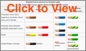
| Protective earth | PE | Green‑Yellow | Green‑Yellow |
| Neutral | N | Blue | Blue |
| Line, single phase | L | Brown | Brown or Black |
| Line, 3‑phase – L1 | L1 | Brown | Brown or Black |
| Line, 3‑phase – L2 | L2 | Black | Brown or Black |
| Line, 3‑phase – L3 | L3 | Grey | Brown or Black |
Legacy codes did not guarantee proper phase rotation; the modern IEC system does. The protective ground is green with a yellow stripe.
Click to expand infographic
United Kingdom – AC Wiring Color Codes
| Function | Label | Color (IEC) | Old UK Color |
|---|---|---|---|
| Protective earth | PE | Green‑Yellow | Green‑Yellow |
| Neutral | N | Blue | Black |
| Line, single phase | L | Brown | Red |
| Line, 3‑phase – L1 | L1 | Brown | Red |
| Line, 3‑phase – L2 | L2 | Black | Yellow |
| Line, 3‑phase – L3 | L3 | Grey | Blue |
United States – AC Wiring Color Codes
The U.S. National Electrical Code (NEC) mandates white or grey for neutral and a bare, green, or green‑yellow stripe for protective ground. All other colors may be used for hots, but local practice is consistent:
| Function | Label | Common Color | Alternative Color |
|---|---|---|---|
| Protective ground | PG | Bare, green, or green‑yellow | Green |
| Neutral | N | White | Grey |
| Line, single phase | L | Black or Red (2nd hot) | |
| Line, 3‑phase – L1 | L1 | Black | Brown |
| Line, 3‑phase – L2 | L2 | Red | Orange |
| Line, 3‑phase – L3 | L3 | Blue | Yellow |
Canada – AC Wiring Color Codes
Canadian Electrical Code (CEC) follows a similar pattern to the U.S., with specific color conventions for single‑phase and three‑phase systems.
| Function | Label | Color (Common) |
|---|---|---|
| Protective ground | PG | Green or green‑yellow |
| Neutral | N | White |
| Line, single phase | L | Black or Red (2nd hot) |
| Line, 3‑phase – L1 | L1 | Red |
| Line, 3‑phase – L2 | L2 | Black |
| Line, 3‑phase – L3 | L3 | Blue |
IEC – DC Wiring Color Codes
DC installations, such as solar arrays and data centers, adopt the same color logic as AC for safety and interoperability. Below is the IEC standard for DC systems, adapted from Cook’s Table 2.
| Function | Label | Color |
|---|---|---|
| Protective earth | PE | Green‑Yellow |
| 2‑wire unearthed DC system | ||
| Positive | L+ | Brown |
| Negative | L- | Grey |
| 2‑wire earthed DC system | ||
| Positive (negative‑earthed) | L+ | Brown |
| Negative (negative‑earthed) | M | Blue |
| Positive (positive‑earthed) | M | Blue |
| Negative (positive‑earthed) | L- | Grey |
| 3‑wire earthed DC system | ||
| Positive | L+ | Brown |
| Mid‑wire | M | Blue |
| Negative | L- | Grey |
United States – Recommended DC Wiring Color Codes
NEC requires grounded neutrals to be white or grey, and protective grounds to be bare, green, or green‑yellow. Hot conductors may be any other color, but local inspectors typically advise black for the first hot and red for the second. The table below follows Wiles’ recommendations. Ungrounded systems are discouraged for safety.
| Function | Label | Color |
|---|---|---|
| Protective ground | PG | Bare, green, or green‑yellow |
| 2‑wire ungrounded DC system | ||
| Positive | L+ | No recommendation (red) |
| Negative | L- | No recommendation (black) |
| 2‑wire grounded DC system | ||
| Positive (negative‑grounded) | L+ | Red |
| Negative (negative‑grounded) | N | White |
| Positive (positive‑grounded) | N | White |
| Negative (positive‑grounded) | L- | Black |
| 3‑wire grounded DC system | ||
| Positive | L+ | Red |
| Mid‑wire (center tap) | N | White |
| Negative | L- | Black |
For precise calculations of wire sizes and resistances, explore our Wire & Resistor Calculators in the Tool section.
Industrial Technology
- Understanding AC Circuits: A Beginner's Guide
- Resistor Color Codes – A Comprehensive Guide to Decoding Value, Tolerance, and E-Series Standards
- Comprehensive Wiring Color Codes Guide – U.S., Europe, Canada & More
- Power Sources: AC and DC Explained
- Emergency Generator Systems: Construction, Installation, Maintenance, and Wiring for Reliable Power
- AC & DC Wiring Color Codes: NEC & IEC Standards for Safe, Compliant Installations
- ABYC Cable & Wire Color Coding Guide for Yachts, Boats, and Marine Wiring
- Capacitor Color Codes Explained – How to Read Capacitor Values & Use the Calculator
- Master Inductor Color Codes: Quick Guide to Decode Inductance Values
- Mastering Resistor Color Codes: Quick Guide for Electronics