


Practical Considerations in Transformer Design: Power, Losses, and Performance
Power Capacity
Transformers must be engineered for robust power coupling, tight voltage regulation, and minimal exciting‑current distortion. Proper conductor gauge prevents overheating during the expected primary and secondary currents.
Ideal Transformer
In theory, an ideal transformer offers perfect coupling, perfect voltage regulation, a sinusoidal exciting current, and no hysteresis or eddy‑current losses. Such an ideal device would, however, be infinitely large and heavy—an impractical concept. Consequently, real‑world transformer design relies on calculated compromises.
High‑voltage transformers, especially step‑up and step‑down types, demand rigorous insulation between the core and each winding, as well as inter‑winding insulation to preserve electrical isolation.
Transformer Ratings
Transformers are specified by primary and secondary voltage ratings, and by a VA or kVA rating that encapsulates the allowable current. For instance, a 120 V primary, 48 V secondary, 1 kVA transformer can handle a maximum winding current of … (include formula?)
Large transformers are almost always rated in VA or kVA; only smaller units list currents in amps.
Energy Losses
Modern power transformers achieve efficiencies above 95 %. Understanding the sources of loss—copper losses, core losses, and mechanical losses—enables designers to target the most significant contributors.
Copper (I²R) Losses
Resistive heating in windings is unavoidable unless superconducting conductors are used. Lengthy windings make this loss non‑negligible, so selecting a higher‑gauge conductor or increasing winding turns can reduce I²R loss, albeit at higher cost, weight, and volume.
Eddy‑Current Losses
Eddy currents circulate perpendicular to the magnetic flux within the iron core, dissipating power as heat. The magnitude of these losses grows with frequency and core cross‑section. Mitigation relies on laminated or powdered cores, each lamination or grain being electrically insulated.
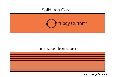
Thin insulated laminations dramatically reduce eddy‑current loss.
Higher‑frequency transformers (e.g., 400 Hz military units) require even thinner laminations or iron powder cores to keep losses acceptable, which increases manufacturing cost.
Hysteresis Losses
Magnetic hysteresis is the energy required to reverse the magnetization of the core each half‑cycle. Choosing a low‑hysteresis alloy and a core cross‑section that keeps flux density well below saturation limits keeps hysteresis losses minimal.
Skin Effect
At higher frequencies, current crowds to the outer surface of conductors, effectively raising resistance and copper loss. Design solutions include larger conductor cross‑section or Litz wire in specialized applications.
Stray Capacitance and Inductance
Dielectric insulation between turns, windings, and core creates parasitic capacitance, which can become significant in high‑frequency signal transformers. Combined with winding inductance, this capacitance defines a resonance frequency that designers must avoid in precision circuits.
Leakage Inductance
Flux that fails to couple between windings appears as series inductance, reducing voltage regulation. In some applications—such as discharge lighting—a deliberate amount of leakage is desirable; otherwise, tight magnetic coupling is pursued.
Core Saturation
Saturation occurs when the core flux density reaches the material limit, causing distortion of the secondary waveform and generation of harmonics. Factors that push a transformer toward saturation include excessive primary voltage, lower operating frequency, or DC bias in the primary.
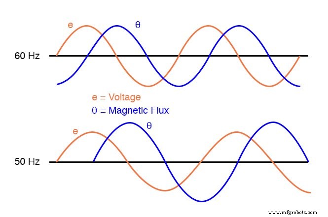
Operating a 60 Hz transformer at 50 Hz raises peak flux, potentially pushing the core toward saturation. Designers add a safety margin by keeping nominal flux density below the core’s saturation point.
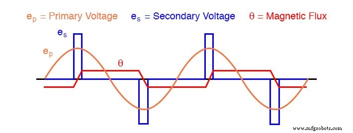
Peaking Transformers
Peaking transformers intentionally saturate at the crest of the voltage waveform to produce sharp voltage pulses. The core is engineered for a very quick, steep saturation, creating a clipped flux waveform and brief secondary pulses.
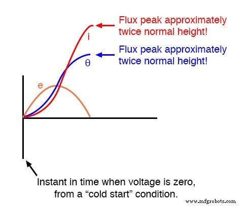
Inrush Current
When a transformer is first energized, the initial current surge—called inrush current—can be several times the steady‑state magnetizing current. This surge is largest when the source voltage is zero at the moment of connection, because the core must build flux from zero to its peak, requiring a sudden increase in winding current.
Inrush current depends on the transformer’s core design, winding resistance, and the exact phase of the applied voltage. Slow‑acting protection devices are therefore standard to accommodate these transient peaks.
Heat and Noise
Heat is generated by copper losses and core losses; if unchecked, it degrades insulation and reduces lifespan. Large power transformers mitigate heat through oil immersion and external radiators, whereas dry transformers are rated by a letter‑class temperature rise (A, B, F, H).
- Class A: ≤55 °C rise at 40 °C ambient
- Class B: ≤80 °C rise at 40 °C ambient
- Class F: ≤115 °C rise at 40 °C ambient
- Class H: ≤150 °C rise at 40 °C ambient
Noise arises mainly from magnetostriction—tiny dimensional changes in the core at twice the line frequency—plus mechanical forces between windings under load. Keeping flux density low and mechanically securing windings are key to quiet operation.
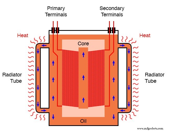
Large transformers are submerged in insulating oil to dissipate heat and dampen noise.
Losses due to Winding Magnetic Forces
Under heavy load, opposing magnetomotive forces in primary and secondary windings generate repulsive mechanical forces. These forces can cause vibration and audible noise if the winding support is inadequate. Design must include robust mechanical anchoring to prevent this.
Key Takeaways
- Transformers are rated in VA/kVA; small units may list currents in amps.
- Copper losses, eddy currents, and hysteresis are the primary sources of inefficiency.
- Higher operating frequencies and harmonics increase core losses and risk overheating.
- Parasitic capacitance and leakage inductance affect voltage regulation and can cause resonance in signal circuits.
- Core saturation—due to high voltage, low frequency, or DC bias—distorts waveforms; design margins mitigate this risk.
- Inrush current peaks when energizing at zero voltage; slow‑acting protection devices are required.
- Heat and noise are controlled through core saturation management, oil cooling, and mechanical support.
Industrial Technology
- Differentiating Exponential Functions of Base e
- Key ADC Design Factors: Resolution, Sampling, and Practical Performance
- Practical Considerations for Operational Amplifiers
- Calculating Electrical Power: Voltage, Current, and Resistance Explained
- Practical Battery Bank Design: Series vs Parallel, Protection, and Charging Best Practices
- Practical Considerations for Selecting and Using Capacitors
- Practical Considerations for Selecting and Using Inductors
- Practical Guide to Power Factor Correction in AC Systems
- Advanced Harmonics Management: Part 2 – Effective Strategies & Measurements
- 10 Essential Tips for Designing Low‑Noise Amplifiers