


Understanding the Skin Effect: Impact on AC Conductors and RF Applications
The Skin Depth of Copper in Electrical Engineering
In alternating‑current (AC) systems, the skin effect causes current to concentrate near the surface of a conductor, effectively reducing the cross‑sectional area that carries current. This phenomenon raises the AC resistance above the DC value, especially at high frequencies.
Illustration: 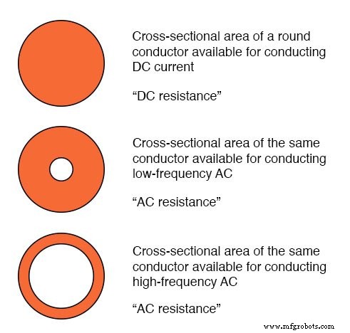
Skin depth decreases as frequency rises.
While the DC resistance reflects the full conductor area, the AC resistance accounts for the skin effect, resulting in a higher effective resistance.
At very high frequencies, the current essentially flows in a thin surface layer—making a solid wire behave like a hollow one.
Hollow Conductors in RF Applications
In radio‑frequency (RF) designs, the skin effect is intentionally leveraged. Because RF currents do not penetrate the core of a solid conductor, engineers often use hollow metal tubes to reduce weight and cost without compromising performance. Most antennas and high‑power RF cables use such tubes.
Example: large inductors in a 50 kW radio transmitter are constructed from hollow copper tubes coated with silver, ensuring excellent conductivity at the skin depth.
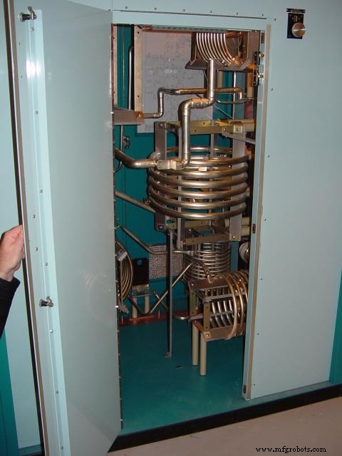
High‑power inductors made from hollow tubes.
Effect of Wire Gauge on Frequency and Effective Resistance
The severity of the skin effect depends on wire gauge. Larger‑gauge conductors exhibit a more pronounced increase in AC resistance relative to DC than smaller gauges at a given frequency.
For frequencies above 1 MHz, the AC resistance can be approximated by:
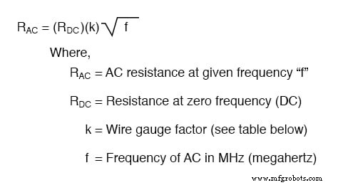
The table below lists the “k‑factor,” a dimensionless value used to estimate AC resistance for round conductors of various American Wire Gauge (AWG) sizes.
Gauge size k factor
| Gauge size | k factor |
|---|---|
| 4/0 | 124.5 |
| 2/0 | 99.0 |
| 1/0 | 88.0 |
| 2 | 69.8 |
| 4 | 55.5 |
| 6 | 47.9 |
| 8 | 34.8 |
| 10 | 27.6 |
| 14 | 17.6 |
| 18 | 10.9 |
| 22 | 6.86 |
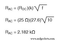
For instance, a 10‑AWG copper wire with a DC resistance of 25 Ω would exhibit an AC (effective) resistance of 2.182 kΩ at 10 MHz, illustrating the dramatic impact of frequency.
RELATED WORKSHEETS:
- Wire Types and Sizes Worksheet
Industrial Technology
- Re‑Platforming in the Cloud: What It Is & How It Drives Efficient Migration
- Edge AI: Accelerating On-Device Intelligence and Transforming Consumer and Enterprise Markets
- Understanding the Fourier Transform: Fundamentals, Applications, and Signal Decomposition
- Harnessing Data in the Internet of Reliability: Strategies for Effective Management
- Inconel vs. Incoloy: Key Differences, Properties, and Ideal High‑Temperature Applications
- Understanding Resistance Welding: Types, Processes, and Industrial Applications
- The Modern Manufacturing Process: Key Techniques and Innovations
- Rheostats vs. Potentiometers: Functionality and Key Differences
- Thermoplastics vs. Thermosets: Key Differences Explained for Material Selection
- Understanding Resistance Wire: Composition, Applications, and Benefits