


Understanding Characteristic Impedance in Transmission Lines
The Parallel Wires of Infinite Length
Consider a pair of parallel conductors extending to infinity, terminated with no load. When the source switch is closed, the line behaves as an open circuit. Does it draw any current at all? See the illustration below.
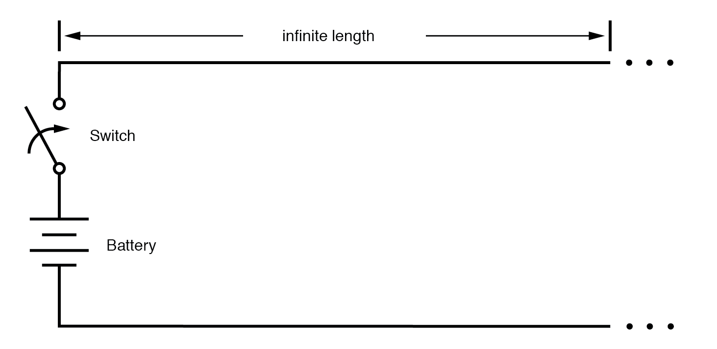
Driving an infinite transmission line.
Even if the conductors were perfect superconductors and thus resistance‑free, the distributed capacitance between them cannot be eliminated. Any two conductors separated by an insulator inherently form a capacitor, as shown below.
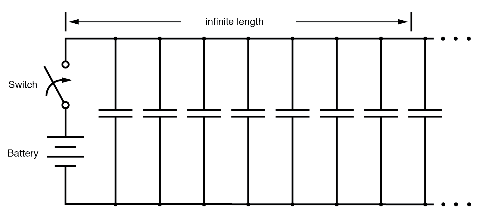
Equivalent circuit showing stray capacitance between conductors.
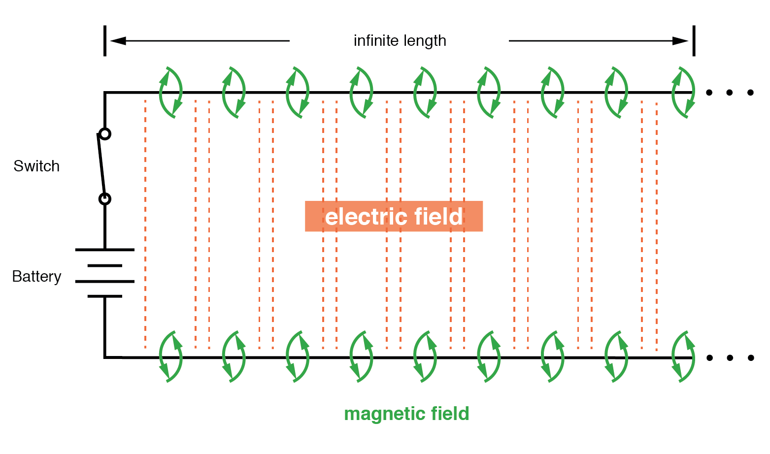
When a voltage is applied across two conductors, an electric field forms and energy is stored in that field. The stored energy opposes changes in voltage, described by the relation i = C dV/dt. Consequently, a sudden voltage step at switch closure forces the line’s capacitance to charge, drawing current from the source. In the idealized case of an instantaneous voltage rise, the current would be theoretically infinite.
Capacitance and Inductance
However, the current drawn by a pair of parallel wires is not infinite because each conductor’s magnetic field generates a distributed inductance along the line. Energy stored in this magnetic field resists changes in current, governed by e = L di/dt. The inductive voltage drop limits the voltage rise across the distributed capacitance, preventing the current from reaching infinity.
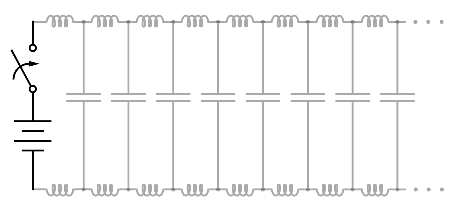
Equivalent circuit showing stray capacitance and inductance.
Voltage charges capacitance, current charges inductance.
The near‑light‑speed transfer of charge between the two conductors creates a wavefront of voltage and current that propagates along the line. As the wave travels, the distributed capacitance and inductance gradually reach their full voltage and current, illustrated below.
Uncharged transmission line.
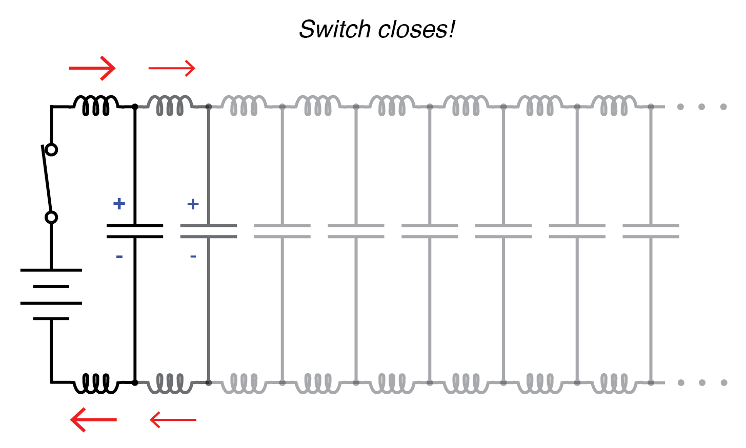
Begin wave propagation.
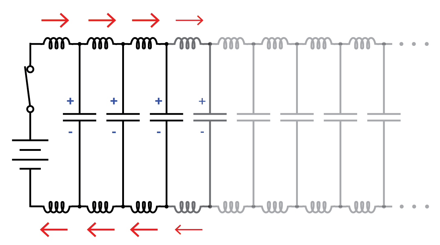
Continue wave propagation.
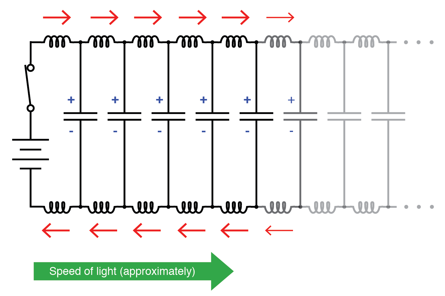
Propagate at speed of light.
The Transmission Line
As a result of these interactions, the infinite pair of wires draws a constant, finite current from the source. The distributed capacitance never fully charges to the source voltage, and the distributed inductance never permits unlimited current. Thus, the conductors behave not merely as passive conductors but as an active circuit component: a transmission line.
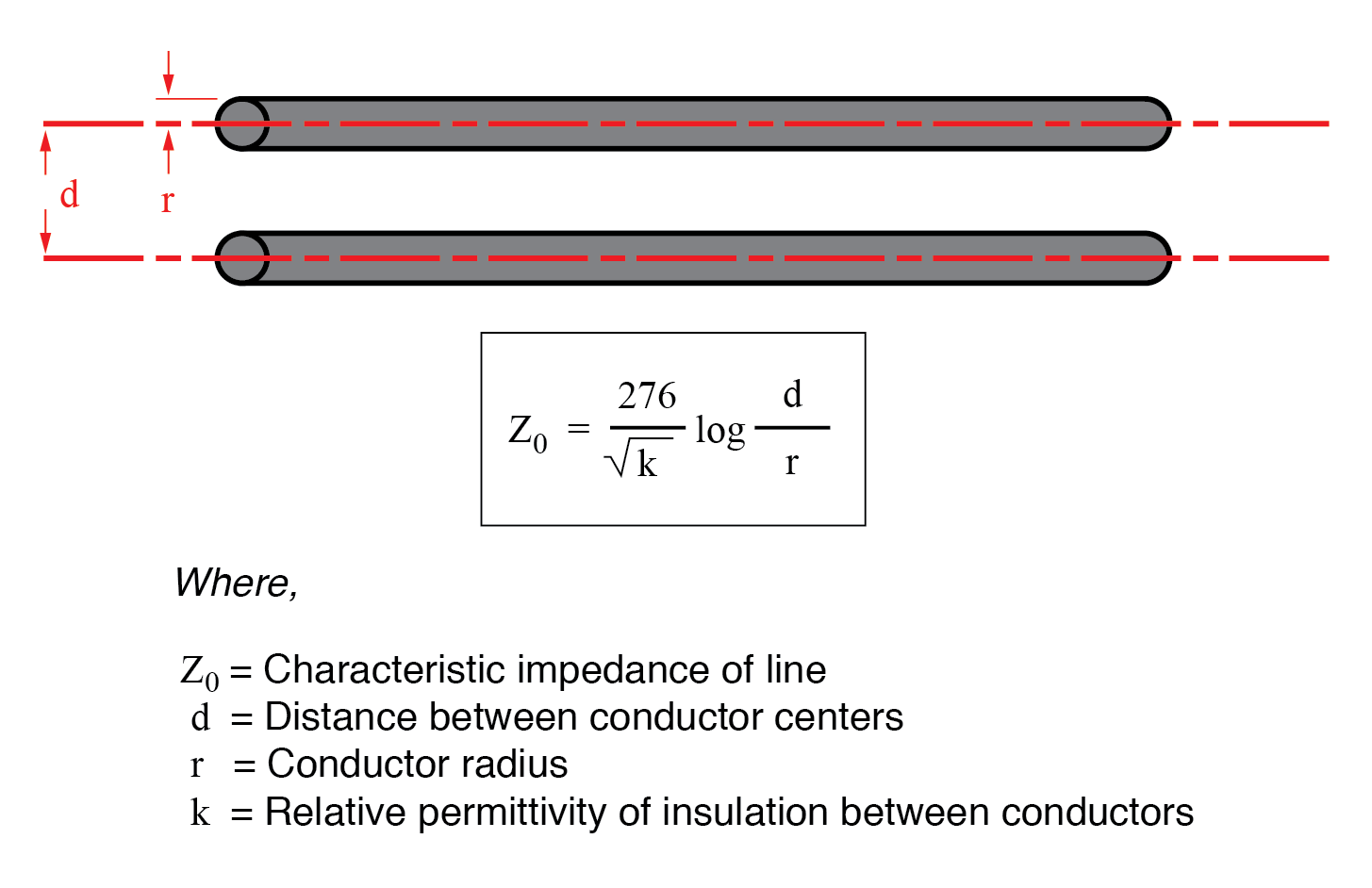
From the battery’s perspective, this line acts like a resistive load, even though it is composed solely of inductance and capacitance (assuming superconducting conductors). The line’s effective resistance is called the characteristic impedance (Z₀), determined entirely by its geometry. For a two‑wire line with air insulation, Z₀ is given by:
For a coaxial line, the expression is:
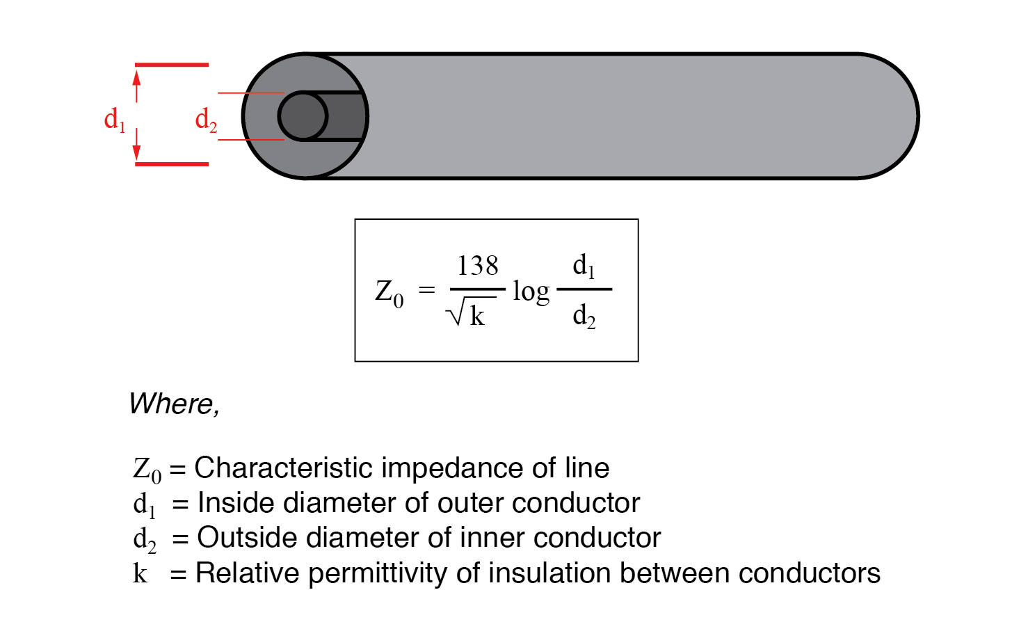
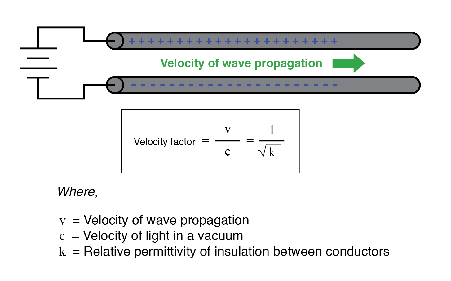
Both formulas require consistent units. If the insulator is not air, the characteristic impedance and propagation velocity change. The ratio of the line’s propagation speed to the speed of light is called the velocity factor, which depends solely on the insulator’s relative permittivity (dielectric constant). It can be calculated as:
The Natural Impedance
Characteristic impedance is also referred to as natural impedance. It represents the equivalent resistance of an infinitely long line due to its distributed capacitance and inductance, causing voltage and current waves to propagate at a fraction of the speed of light.
From the first two equations, we see that Z₀ increases as the spacing between conductors grows. Increasing the gap reduces capacitance and increases inductance, resulting in a higher impedance and lower current for a given voltage. Conversely, bringing the conductors closer increases capacitance and decreases inductance, lowering impedance and raising current.
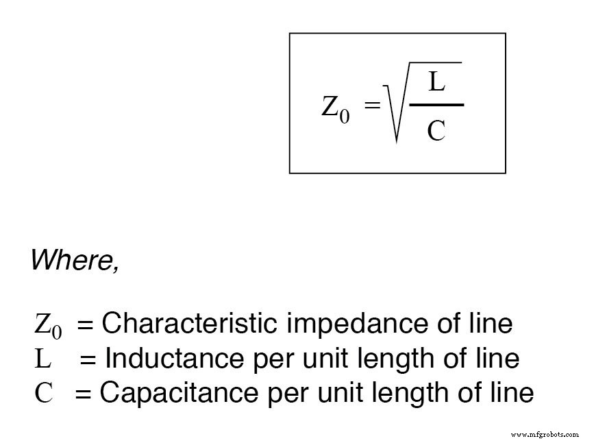
When there are no dissipative losses (ideal dielectric, superconducting conductors), the characteristic impedance equals the square root of the inductance per unit length divided by the capacitance per unit length:
Review
- A transmission line is a pair of conductors whose distributed capacitance and inductance endow it with unique electrical properties.
- When a voltage step is applied, voltage and current waves propagate along the line at nearly the speed of light.
- For a DC voltage applied to an infinitely long line, the line behaves like a constant resistive load.
- The characteristic impedance (Z₀) is the resistance an infinite line would exhibit, independent of dielectric leakage or conductor resistance.
- The velocity factor, ranging from 0.66 to 0.80 for typical two‑wire lines and coaxial cables, is the reciprocal of the square root of the insulator’s relative permittivity.
Related Worksheets
- Characteristic Impedance Worksheet
Industrial Technology
- Voltage‑to‑Current Signal Conversion: A Practical Transconductance Amplifier Design
- Understanding Voltage and Current: The Foundations of Electrical Flow
- Understanding Insulator Breakdown Voltage and Dielectric Strength
- Capacitors & Calculus: How Voltage Change Drives Current
- Understanding Inductor Transient Response: Energy, Current, and Voltage Dynamics
- Advanced Analysis of DC Reactive Circuits with Non‑Zero Initial Conditions
- Understanding AC Inductor Circuits: Reactance, Phase Shift, and Power Dynamics
- Analyzing Series Resistor‑Inductor AC Circuits: Impedance, Phase, and SPICE Verification
- Pure Resistive AC Circuits: Voltage and Current In Phase
- AC Capacitor Circuits: Capacitive Reactance, Phase Shift, and Power Behavior