


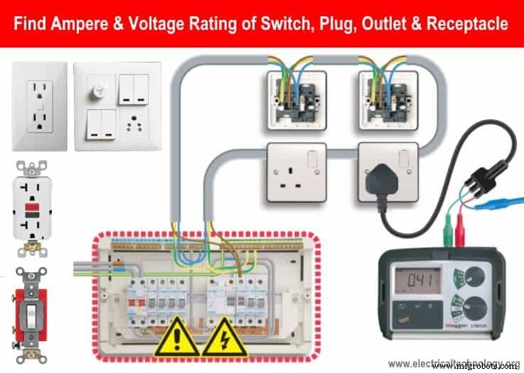
Determine the Correct Voltage & Ampere Ratings for Switches, Plugs, and Outlets
How to Find the Proper Ampere and Voltage Rating of Switch, Socket-outlet, Receptacle, and Plug etc.?
Switches, outlets, plugs, receptacles, connectors, GFCI etc are designed and rated with different rating having different electrical characteristics. The rating of switches depends on multiple factors i.e. the material and insulation class used for switch contacts, size and space between the contacts and specific application etc.
There are two main rating for a switch:
- Current Rating: The indicated current rating in amperes on switch nameplate shows the maximum ampacity the switch can carry in the connected circuit.
- Voltage Rating: This is the maximum voltage a switch can be used and installed in the circuit.
Let’s see what are the rules and regulations about the switch rating and how to select the proper size of switch related to the current and voltage capacity.
- Related Post: How to Find the Proper Size of Circuit Breaker? Breaker Calculator & Examples
Current Rating of a Switch in Amperes:
All the switches, breakers, plugs, outlets, connectors and wires etc having two amperage rating.
Safe maximum: switches, plugs, breakers, connectors, wires etc have a safe max amps.
- Maximum Current: A 15 Amps switch maximum current rating is 15 Amps i.e. it can be installed on circuit having maximum 15A load current.
The maximum current rating depends on the circuit voltage and should never exceed the exact current rating. If it exceeds, it will melt and weld the switch contacts and the switch will be useless. If there is no breaker, it may lead to damage the connected device even cause a dangerous fire. In simple words, A 15A switch should not be used for 20A load current.
Generally, residential and household devices are operated by 15A (14 gauge) load circuits but occasionally, 20A (12 gauge) devices are also used in case of single phase 120V AC supply. Mostly, 30A (10 gauge) circuits are used for 240V AC supply according the load wattage i.e. water heaters etc.
- Related Post: How to Find The Suitable Size of Cable & Wire ? – Solved Examples
Most residential devices are 15A, but on occasion a 20A device may be appropriate.
- Safe Maximum Current: A 30 Amps switch safe maximum current rating is 24 Amps. i.e. it can be installed on a circuit having maximum 24A load current such as water heater circuit having 30A switch while the load current is 24A or below. It can be calculated as follow:
Safe Maximum Current: Maximum Current x 80%
Related Switch Wiring Tutorials:
- How To Wire Switches In Series?
- How To Wire Switches in Parallel?
Example: What is the safe maximum current in amperes of a 15A switch?
Solution:
- Safe Max Current = Max Current x 0.8
- Safe Max Current = 15A x 0.8
- Safe Max Current = 12A
It means, a 15A switch can be used safely for a 12A load current. Although, the 15A swicth can be used for exact 15A switch for non-continuous (non-simultaneous) load. While in case of continuous load, a 15A switch should be used for maximum of 12A load circuit.
If the current rating is same for both 120V and 240V, the load value in volt amperes (VA) and Watts (W) may be different. for instance:
- 20A, 120V switch safe max current value is 16A. The load in Watts this switch can safely handle = 16A x 120V = 1920 W.
- If the current rating is same while we increase the voltage to 240V, then = 16A x 240 = 3840 Watts. (Note: This is example calculation. Use 30A switches, plugs and outlets on 240V supply voltage.
- Similarly, the safe max amp rating of 15A switch is 12A and the load which can be handled by this switch is 12A x 120V = 1440 Watts.
Related Calculators:
- Wire & Cable Size Calculator in AWG
- Electrical Wire & Cable Size Calculator (Copper & Aluminum)
Voltage Rating of a Switch in Volts:
Voltage rating of a switch shows the maximum allowable voltage of the circuit where the switch has to be used for different loads.
A switch can be rated for AC voltage, DC voltage or both having different values and ampacity. For example, a switch can be rated for 240V AC, 230V AC, 15 Amps, 120V DC, 20A etc. Read the user manual or nameplate data on the switch before installation.
The supply voltage should never exceed the voltage rating of switch. In other words, If we connect an 120V switch on 500V, the applied voltage may jump over the open contacts (and overheat due to overvoltage) of the circuit and connect the load to the supply voltage. It will lead to spark as well which may cause fire. The breaker will open the circuit and stop the operation if current exceed the limit due to excessive voltage as compared to the rated voltage. In short, an 120V and 230V rated switches should not be used for 240 and 480V respective.
- Related Post: How to Find the Size of Earth Conductor, Earthing Lead & Earth Electrodes?
How Much Switches, Receptacles and Socket-outlet Can be installed on 15A & 20A Circuits?
- For secure and smooth operation, a single outlet should be connected to the 15A circuit.
- To know the safe number of socket outlets or receptacles, assign a 1.5A to each one as follow.
- 20A Circuit / 1.5 A = 13 No of socket outlets and receptacles.
- 15A Circuit / 1.5A = 10 Number or receptacles or socket-outlet.
For 15A and 20A circuit, use 14 and 12 gauge wire respectively. In case of outdoor, laundry, kitchen, bathroom or watery areas, it is the code to use GFCI and ground fault interrupting receptacles for maximum protection.
- Related Post: How to Wire a Single Element Water Heater and Thermostat?
Sizing ATS and Disconnect Switches
Disconnect Switch Rating
According to the article and section of NEC-430:
- The suitable size of disconnect switch should be equal or grater than 115% of the rated motor full load current.
- If we consider the HP or Watts rating for disconnect switch, the rated HP (or Watts) of disconnect switch should equal or greater than the rated motor HP or watts at the rated voltage.
Automatic Transfer Switch (ATS) Rating
Example: What is the proper size of ATS for a 210kW, 208V three phase AC supply.
Solution:
- Current in three phase AC circuits = I = P / (V x √3
- I = 210kW / (208V x 1.732)
- I = 583 Amp.
You may use then 600A (three poles) automatic transfer switch for 210kW heating loads.
- Related Post: How to Wire Auto & Manual Changeover & Transfer Switch – (1 & 3 Phase)
NEC and IEC Rules About Switch Rating
- 14 Gauge wire should be used for 15A switch, plug or outlet and household load such as lighting circuits.
- 12 Gauge wire should be used for 20A switch.
- 10 gauge wire should be used for 30A switch (mostly 240V) and 30A circuit breaker.
- A switch or plug rated for 15A, 120V can be used on max of 15A, 120V load circuit.
- A switch or outlet rated for 15A, 120V can’t be used on 20A, 120V load circuit.
- A switch rated for 20A, 120V can be used on 15A and 20A, 120V load circuit.
- It is against the rules to use 120V Switch or outlet on 240V circuit and vice versa.
- A 240V switch can be only used on 120V circuit if the current rating is suitable for the load currents.
- It’s not OK to use the 120V switch or plug on 240V even the current rating is suitable.
- Switches much be connect and wire on the Phase (Live or Line) wire. i.e. Only phase wire should be disconnect through the switch to ON/OFF the connected circuit.
- It’s against the rules to wire the switch on Neutral Wire.
- A switch rated for 15A, 120V can be used on 20A, 120V circuit from the distribution board.
- A switch rated for 20A, 120V can’t be used on household 15A, 120V supply circuit.
- 15A devices (load) can be plugged into a 20A outlet, but not vice versa.
- An over sized switch is OK but lower rating than the load current can melt the switch contacts.
- For different level of protection, the designer and electrician must select appropriate IP rated switch according to the IEC 60529 such is IP60, IP65, and IP67 etc.
- A switch rated for 10A, 120V AC designed for pure resistive load can be used on 6A, 120V AC for inductive load which never affect the life expectancy of the switch i.e. 100000 operation or 25000 cycles in both cases.
Good to know:
A switch rated for:
- 120V can only be used for 120V.
- 240V can be used for 120V, 240V but not for 277V (Commercial applications)
- 120-277 can be used for 120V, 240V and 277V.
Related Post: Electrical Installations – Standards & Regulation around the World
Safety Precautions
Warning & Precautions
- Disconnect the power before replacing, repairing, troubleshooting, maintenance and installation electrical appliances and equipment.
- Switches muse be connect through the phase (live or line) wire (NOT ON NEUTRAL). So that, it can control the ON/OFF operation of the circuit by disconnected the line or phase supply.
- Use the proper size of cable and wire for electrical wiring installation.
- Failure to do so can result in electrical shock, serious injury, fire or even death.
- Perform a continuity test for switch terminal before wiring and installation. Use 10 gauge wire for 240V and 12 Gauge for 120V in the wiring installation.
- Follow your regional wiring color codes i.e. IEC or NEC.
- Please follow the user manual instruction, local area codes or contact a licensed electrician for proper installation.
- The author will not be liable for any losses, injuries, or damages from the display or use of this information or if you try any circuit in wrong format. So please! Be careful because it’s all about electricity and electricity is too dangerous.
Industrial Technology
- Using a Transistor as an Electrically Controlled Switch
- Voltage‑to‑Current Signal Conversion: A Practical Transconductance Amplifier Design
- Understanding Voltage and Current: The Foundations of Electrical Flow
- Understanding Insulator Breakdown Voltage and Dielectric Strength
- Understanding AC Inductor Circuits: Reactance, Phase Shift, and Power Dynamics
- AC Capacitor Circuits: Capacitive Reactance, Phase Shift, and Power Behavior
- Understanding Characteristic Impedance in Transmission Lines
- Step-by-Step Guide to Wiring a GFCI Combo Switch and Outlet: Diagrams & Installation Tips
- Professional Wiring Guide for Combo Switch/Outlet Devices – Diagrams & Installation Tips
- Step‑by‑Step Guide: Wiring a Household Outlet Receptacle with Clear Diagrams