


Finite-Length Transmission Lines: Impedance, Reflections, and Termination
A transmission line of infinite length is a useful theoretical construct, but every real cable has a finite span, which changes its behaviour.
When I measured a 50 Ω RG‑58/U cable with an ohmmeter years ago, the finite length caused the measurement to read “open” (infinite resistance). If the cable were truly infinite, the resistance between conductors would equal its characteristic impedance of 50 Ω.
The characteristic impedance—often called surge impedance—is critical even for short lengths. When a transient voltage (“surge”) is applied to a line, the current that flows is simply the surge voltage divided by the surge impedance (I = E/Z). This Ohm’s‑law relationship holds only for the brief interval before the signal reaches the line’s end.
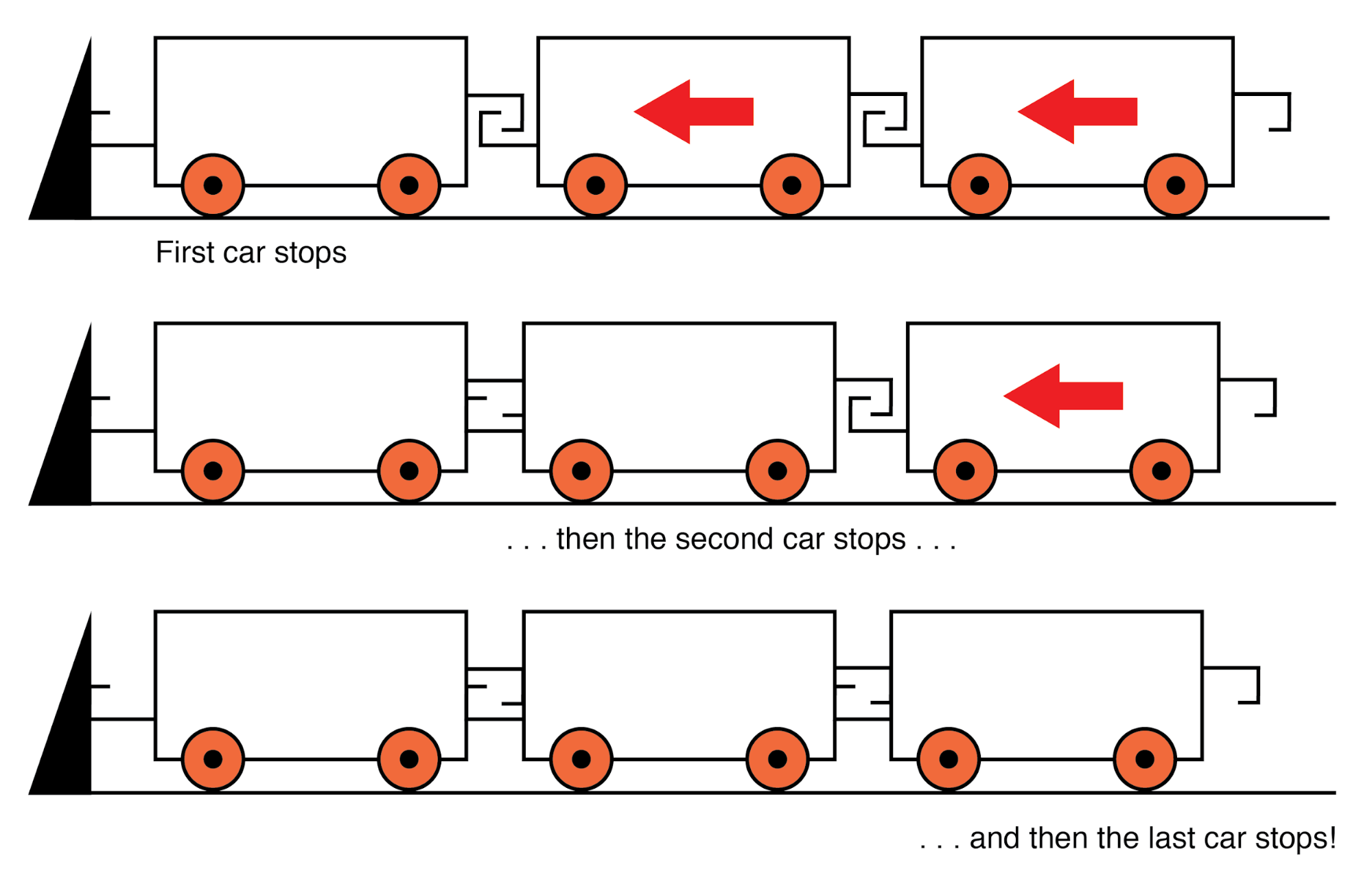
At the line’s terminus, if the end is open‑circuited, the propagating current wave must stop because there is no path for the charge to flow. This sudden halt causes a “pile‑up” of charge carriers that travels back along the line, analogous to a train stopping sequentially car by car when the first car hits a wall.
A signal launched from the source to the load is an incident wave; the return signal that bounces back toward the source is a reflected wave. Once the reflected wave reaches the source, the line behaves as a simple open circuit. Because the propagation is extremely fast—an 8‑mile cable at a velocity factor of 0.66 takes only 8.1 µs one way and 16.3 µs round‑trip—an ohmmeter can never capture the brief resistive phase.
Why Incident and Reflected Waves Matter
High‑speed instruments, such as time‑domain reflectometers (TDRs), exploit the round‑trip time to measure cable length or locate faults. The principle is identical to sonar: send a pulse and measure the echo time.
Short‑circuited ends reflect voltage waves back to the source because voltage cannot exist between two electrically common points. The reflected wave turns the entire line into a short circuit for the duration of the round‑trip.
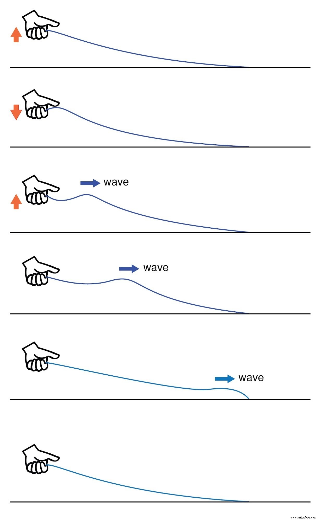
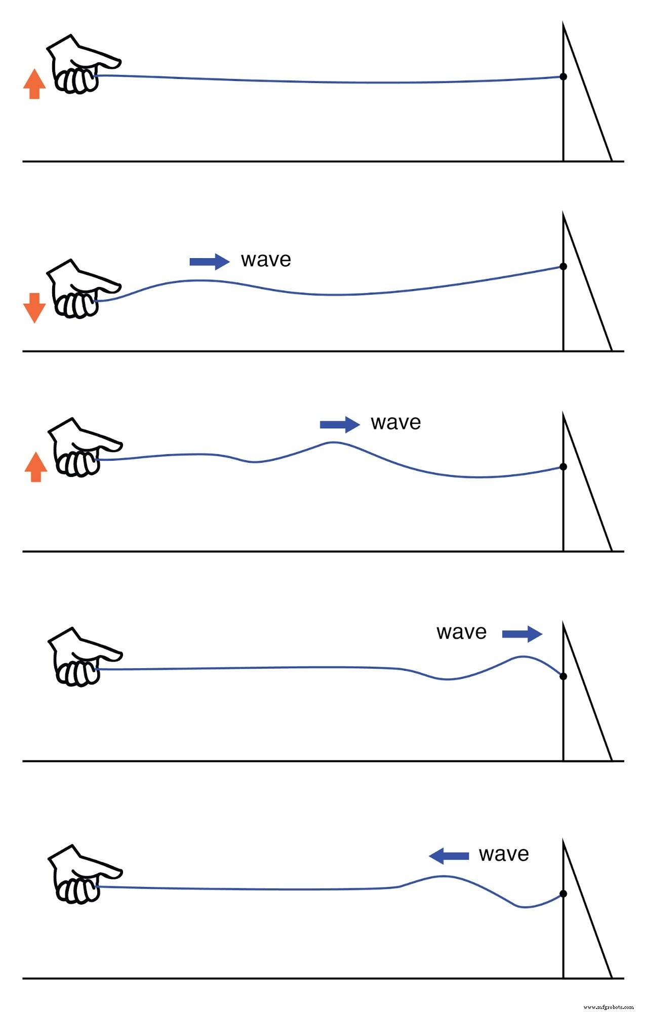
A simple analogy is a rope whipped in a single, rapid motion. The disturbance travels along the rope and dissipates, or if the far end is fixed, a second wave reflects back to the hand.
Lossy transmission line.
Reflected wave.
In practice, a transmission line is intended to deliver electrical energy from source to load. Any reflected energy represents loss and degrades signal‑to‑noise ratio, so minimizing reflections is a primary design goal.
Eliminating Reflections
Reflections vanish when the load impedance exactly matches the line’s characteristic impedance. A 50 Ω coax cable that is open‑ or short‑circuited reflects all incident energy, but terminating it with a 50 Ω resistor absorbs the wave completely.
Conceptually, an infinite‑length line behaves like a 50 Ω resistor as seen from one end. A finite line behaves as a 50 Ω resistor only for a fleeting instant; thereafter it presents an open or short depending on the termination.
Adding a matching termination restores the infinite‑length behaviour for all time.
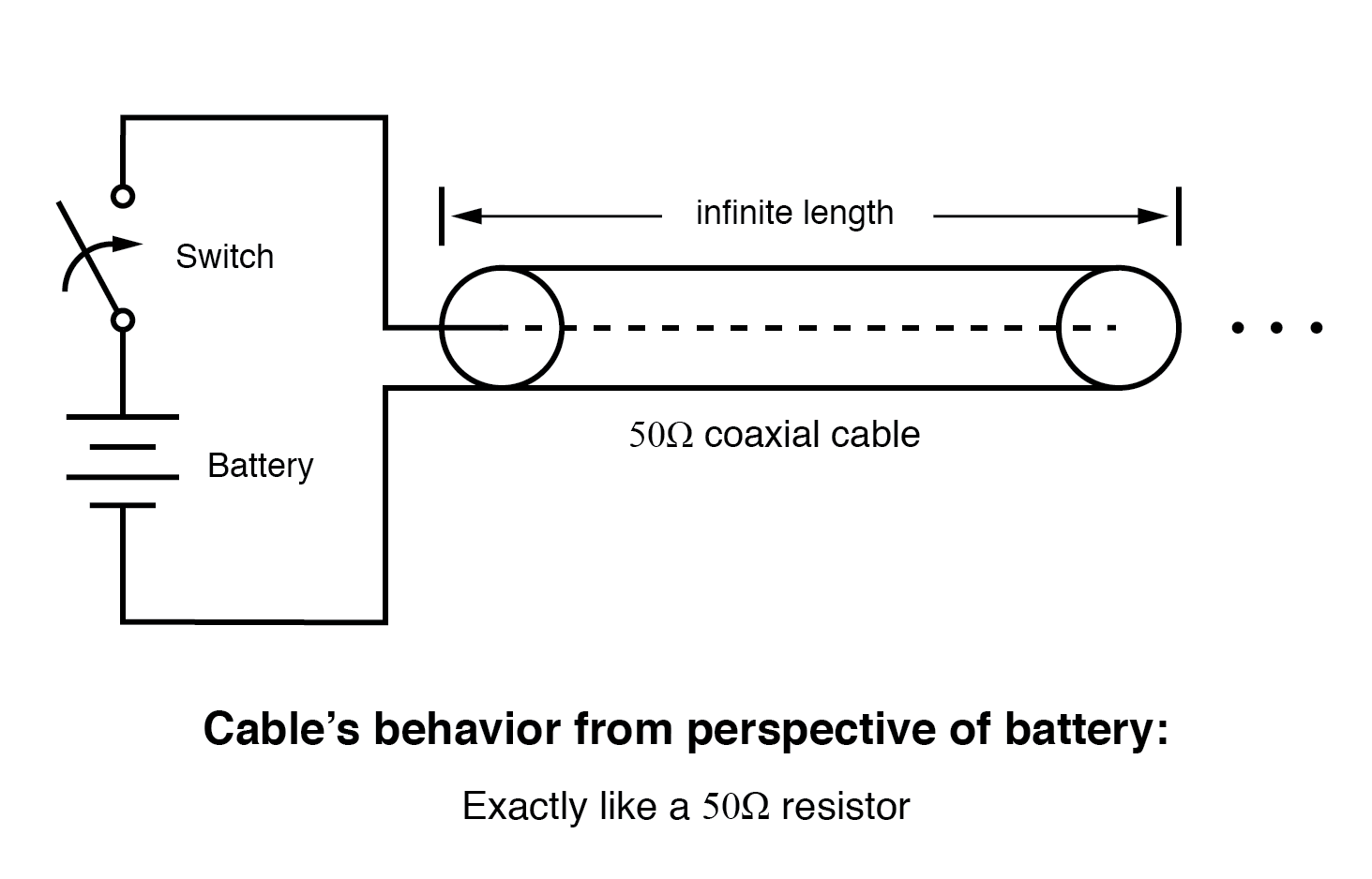
Infinite transmission line looks like resistor.
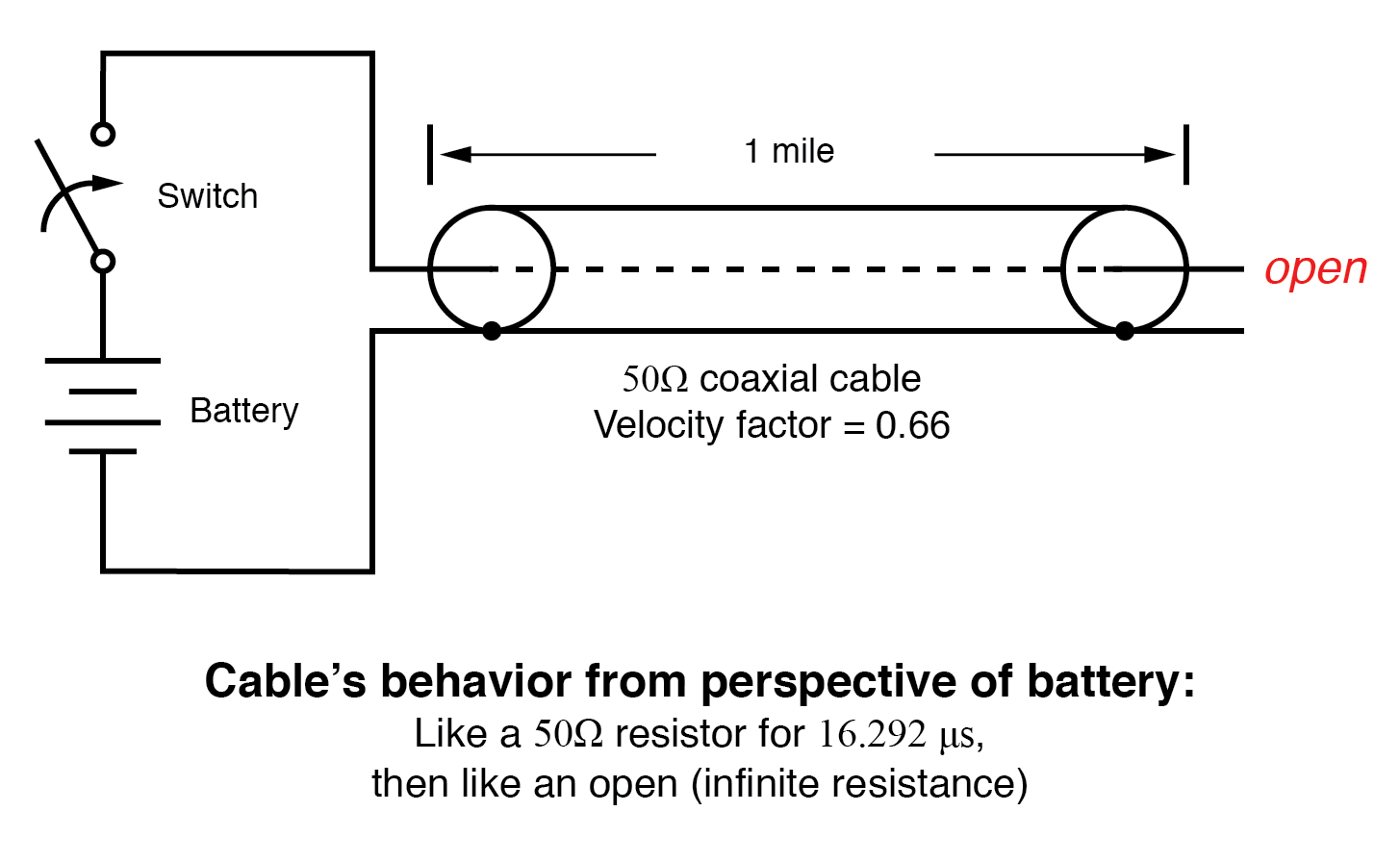
One mile transmission.
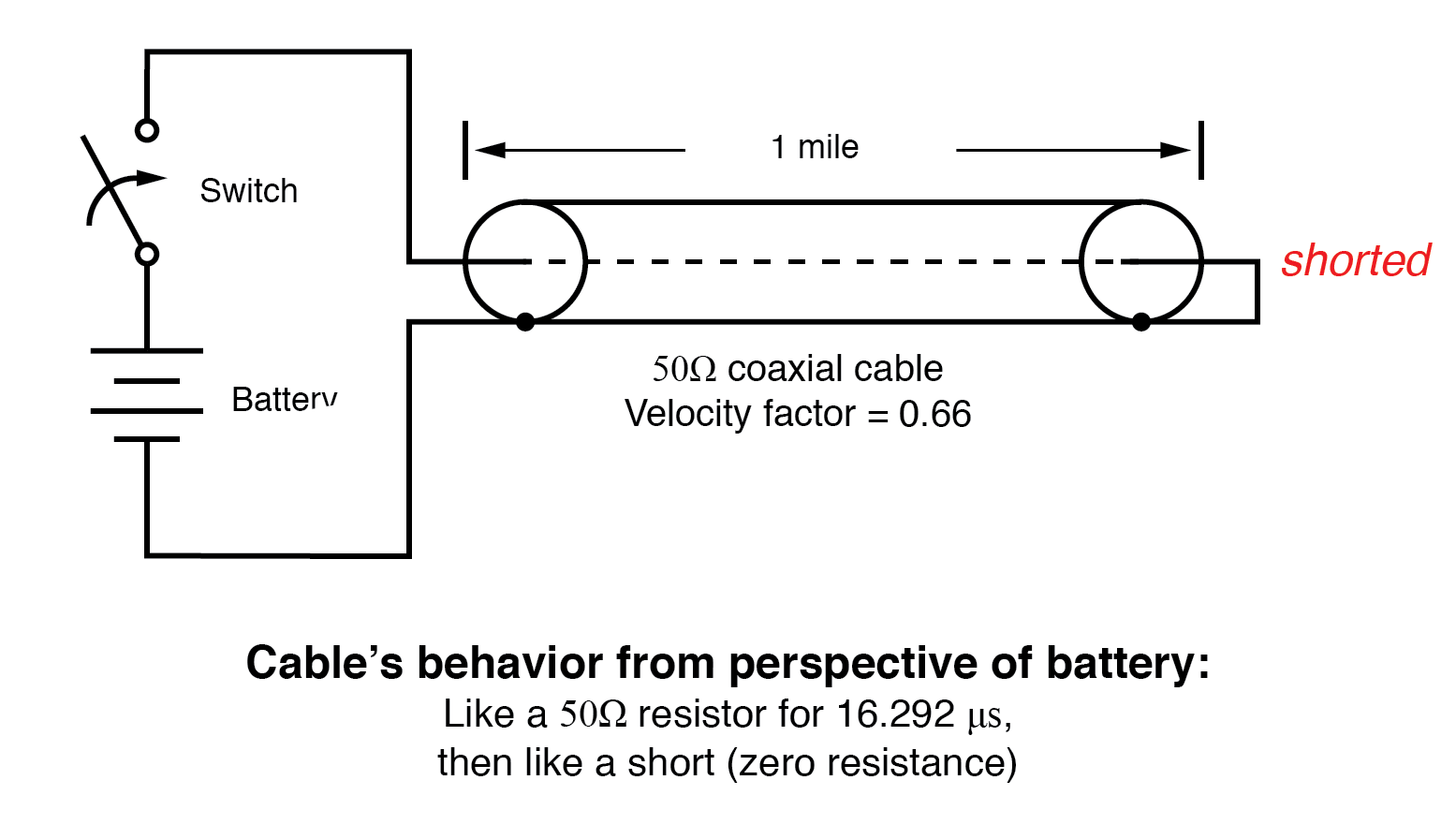
Shorted transmission line.
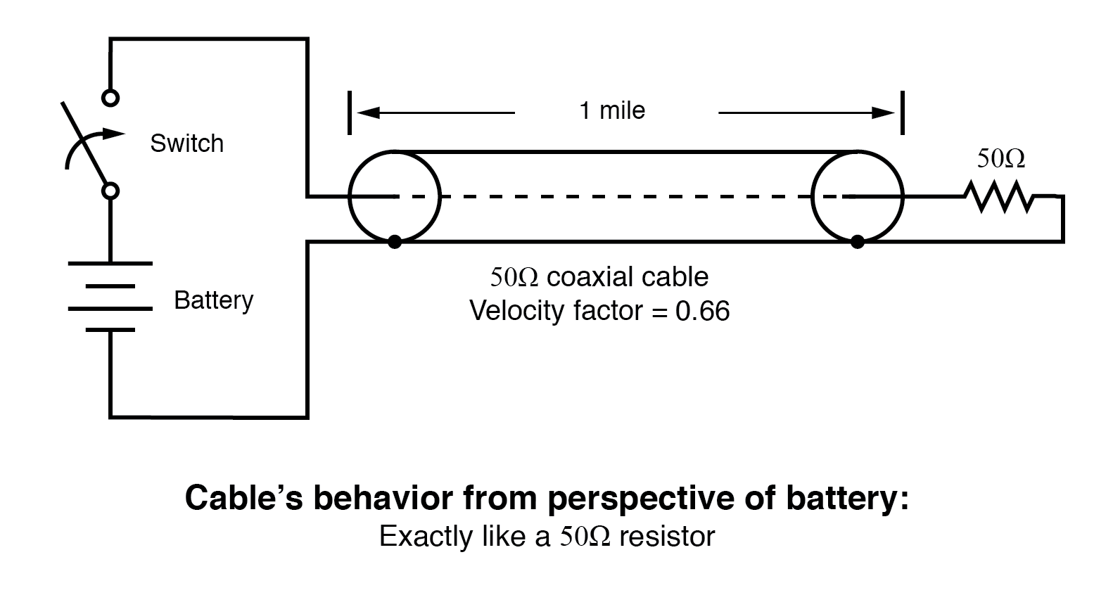
Line terminated in characteristic impedance.
Matching the termination to the line’s natural impedance makes the source perceive the line as infinitely long because the terminating resistor can dissipate energy just as an ideal infinite line can absorb it.
Even a slight mismatch—whether the termination is slightly higher or lower than the characteristic impedance—produces partial reflections. If the source’s internal impedance also mismatches the line, the reflected wave can bounce back toward the load, appearing as an extra pulse.
Review- Characteristic impedance, also called surge impedance, represents the temporary resistive behaviour of any transmission line.
- A finite‑length line behaves as a constant resistor to a DC source only briefly; its measured impedance thereafter depends on the termination.
- Transient signals applied to an open‑ or short‑circuited line generate reflected waves. Incident waves travel from source to load; reflected waves travel back from load to source.
- Imperfectly matched terminations also produce reflections.
- Matching the line’s characteristic impedance eliminates all reflections, making the line appear infinite.
- Mismatched source impedance can cause re‑reflections that mimic additional transmitted pulses.
Industrial Technology
- Understanding Decoders: Types, Truth Tables, and Practical Applications
- Understanding Long and Short Transmission Lines in Electrical Engineering
- Waveguides Explained: Fundamentals, Modes, and Practical Applications
- Mastering C# Comments: Types, Best Practices, and XML Documentation
- Bosch Pioneers Industry 4.0: Smartwatch‑Enabled Assembly Lines Boost Efficiency
- Understanding Line Efficiency: Key Metrics for PCB Production
- Understanding Corona Discharge: Impact on Overhead Transmission Lines
- Understanding PCB Transmission Lines: Design, Function, and Applications
- GD&T Explained: Profile of a Line vs. Profile of a Surface
- Deburring Robots: Efficiently Removing Welding Lines for Stronger Products