


Waveguides Explained: Fundamentals, Modes, and Practical Applications
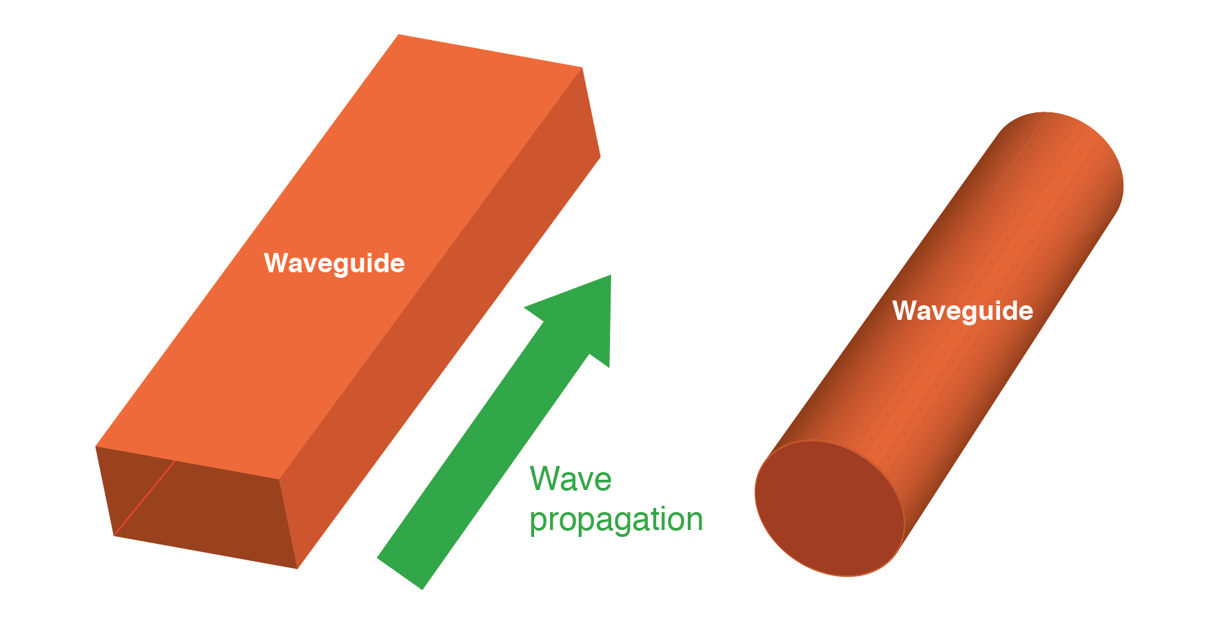
A waveguide is a specialized transmission line consisting of a hollow metallic tube. The metal walls provide distributed inductance, while the internal air gap supplies distributed capacitance.
Waveguides conduct microwave energy with lower loss than coaxial cables.
Waveguides are practical only for signals at very high frequency, where the wavelength is comparable to the guide’s cross‑section. At lower frequencies they lose effectiveness as transmission lines.
Usage of Waveguides as a Transmission Line
When used as transmission lines, waveguides are considerably simpler to manufacture and maintain than two‑conductor cables, especially coaxial ones.
With only a single conductor—the waveguide’s shell—there is no need to control conductor‑to‑conductor spacing or dielectric consistency; the only dielectric is air.
Moisture is less problematic in waveguides than in coaxial cables, so they often omit gas filling.
Waveguides act as conduits for electromagnetic energy, directing the wave rather than conducting it in the conventional sense.
All transmission lines function as energy conduits, but propagation in a single‑conductor waveguide differs fundamentally from that in two‑conductor lines.
What is Transverse Electric and Magnetic (TEM) Wave Propagation?
All electromagnetic waves consist of electric and magnetic fields that propagate together, perpendicular to each other. In a standard transmission line, both fields are transverse to the direction of travel.
This transverse mode, called TEM (Transverse Electric and Magnetic), exists only in two‑conductor lines and dominates when the line’s cross‑section is small relative to the wavelength.
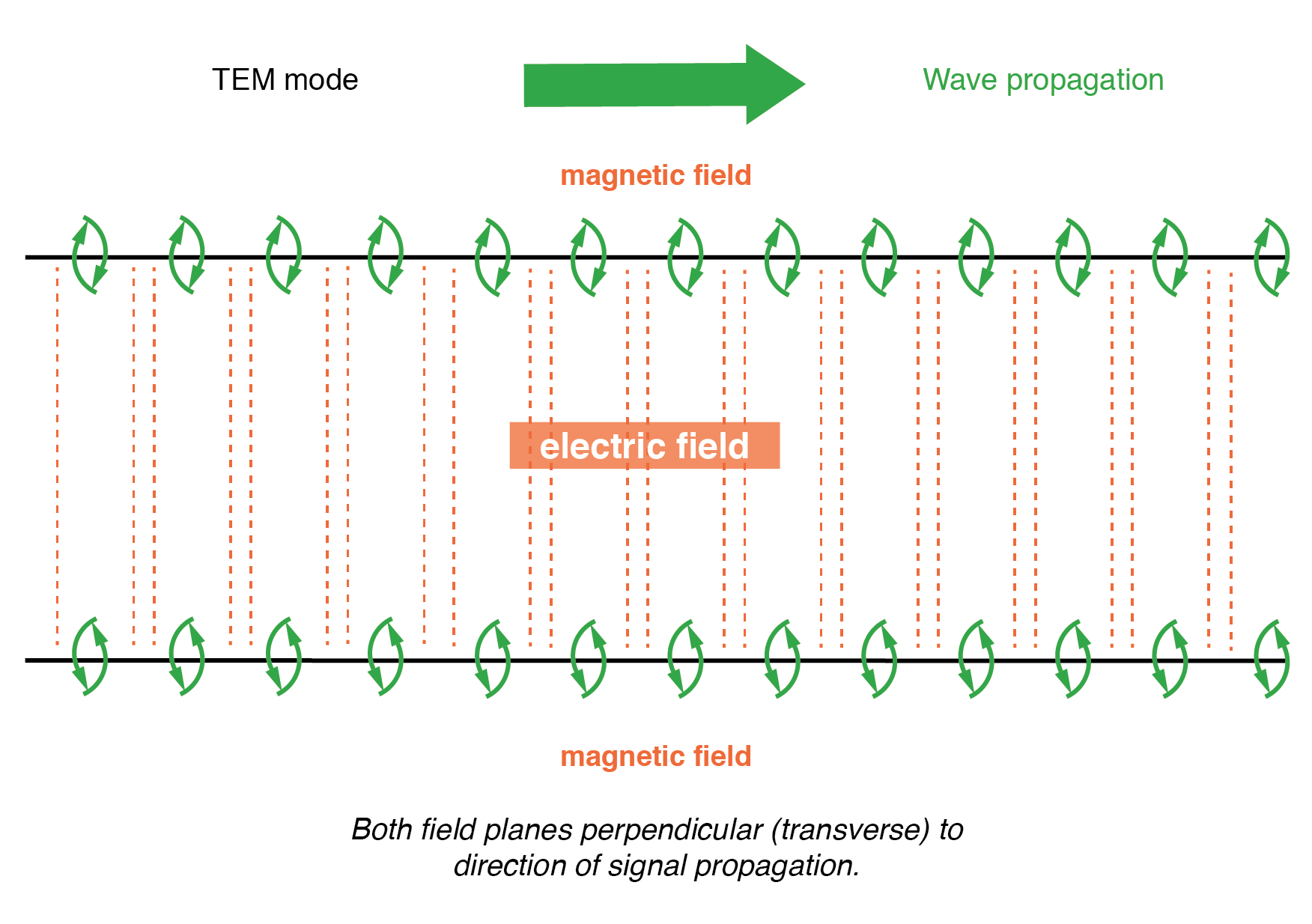
Twin lead transmission line propagation: TEM mode.
At microwave frequencies (100 MHz–300 GHz), two‑conductor lines operating in TEM mode become impractical over significant lengths.
Lines small enough to maintain TEM mode at microwave frequencies suffer from low voltage ratings and high parasitic losses due to skin effect and dielectric loss.
Fortunately, at these short wavelengths alternative propagation modes are available that are less lossy when a conductive tube is used instead of parallel conductors. This is where waveguides become advantageous.
When an electromagnetic wave travels down a hollow tube, only one of the fields—either electric or magnetic—remains transverse to the propagation direction. The other field loops longitudinally but stays perpendicular to the transverse field. The field that remains transverse determines whether the wave propagates in TE (Transverse Electric) or TM (Transverse Magnetic) mode.
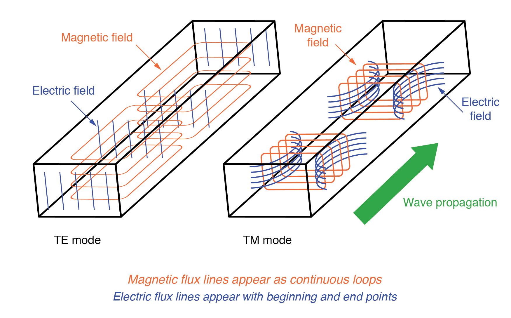
Waveguide (TE) transverse electric and (TM) transverse magnetic modes.
Each waveguide supports multiple mode variations, but a comprehensive discussion is beyond the scope of this article.
How Are Signals Introduced to and Extracted from Waveguides?
Signals are typically coupled into or out of a waveguide using small antenna‑like devices inserted into the guide. These couplers can be dipoles—two open‑ended stubs of appropriate length—or a single stub (a half‑dipole, similar to a whip antenna, ¼ λ in physical length), or a short loop of wire terminating on the guide’s inner surface.
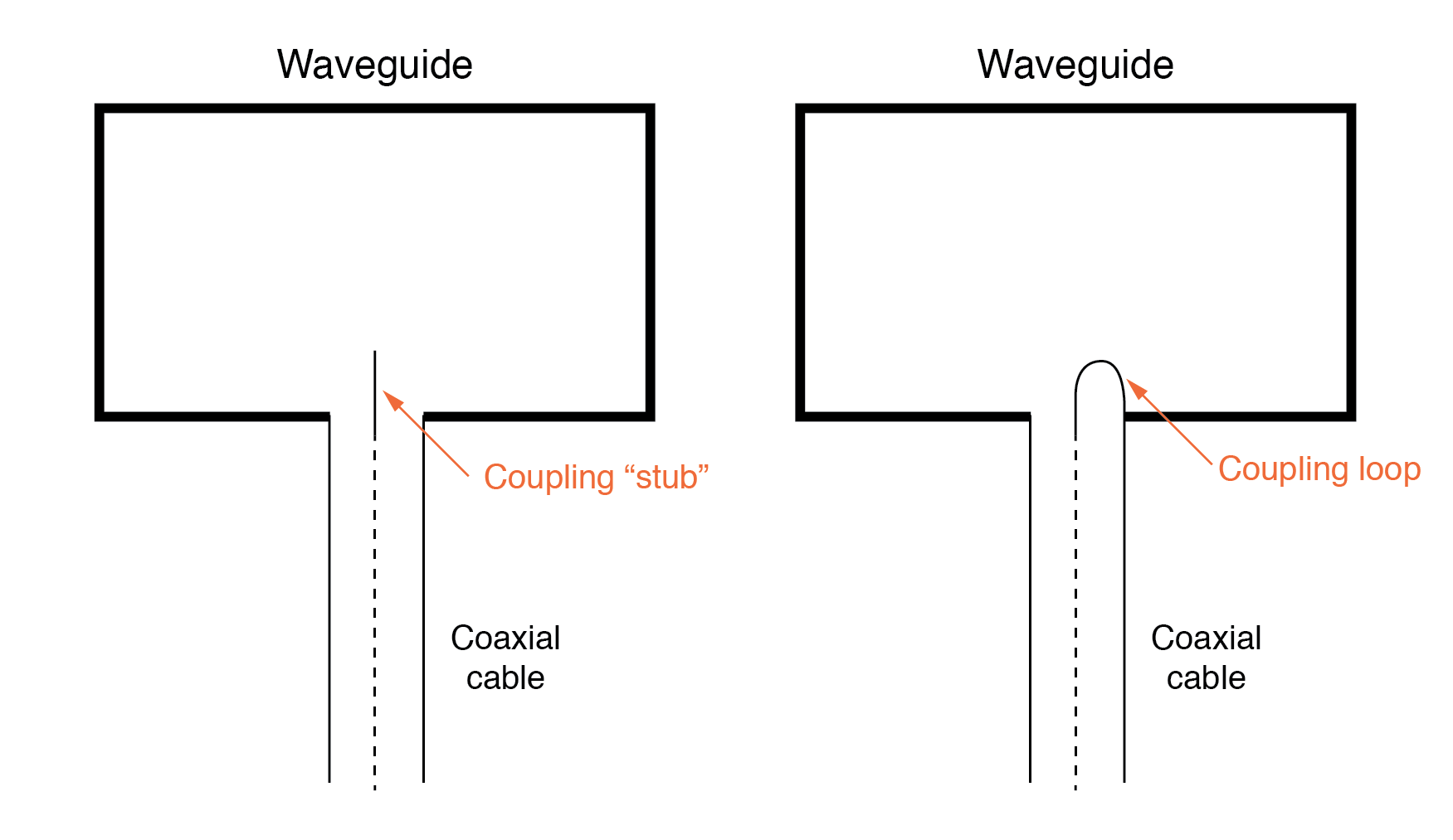
Stub and loop coupling to waveguide.
In some devices, such as inductive output tubes (e.g., the klystron), a cavity of conductive material intercepts electromagnetic energy from a modulated electron beam without direct contact.
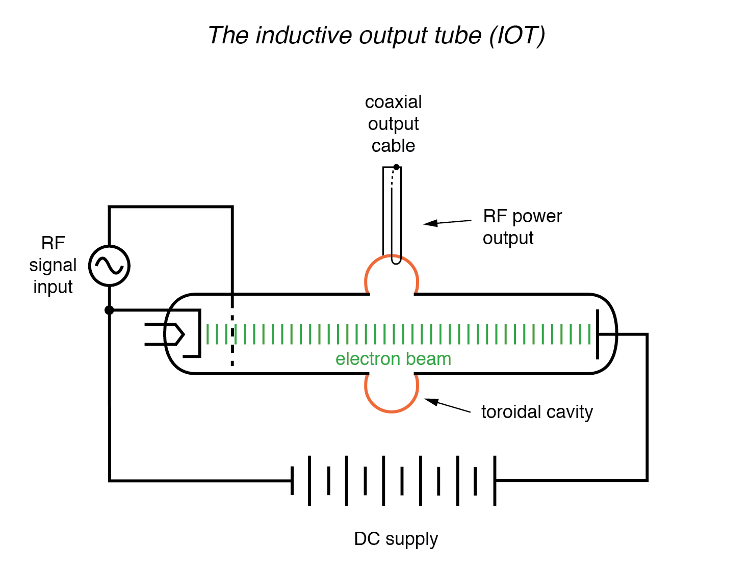
Klystron inductive output tube.
What is a Cavity Resonator?
Like transmission lines, a dead‑ended waveguide can resonate at specific frequencies. When used as such, the device is called a cavity resonator.
Inductive output tubes employ toroid‑shaped cavity resonators to maximize power transfer between the electron beam and the output waveguide.
A cavity’s resonant frequency can be tuned by adjusting its physical dimensions. Manufacturers incorporate movable plates, screws, and other mechanical elements to provide coarse frequency adjustment.
If a resonant cavity is open on one end, it functions as a unidirectional antenna.
The following photo shows a homemade waveguide constructed from a tin can, used as an antenna for a 2.4 GHz Wi‑Fi (802.11b) signal.
The coupling element is a quarter‑wave stub: a solid copper wire about 1‑1/4 inches long extending from the center of a coaxial connector into the can.
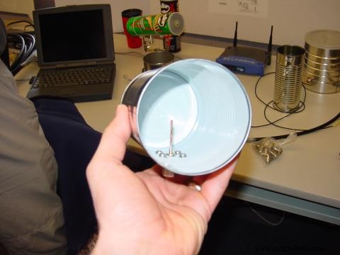
Can‑tenna illustrates stub coupling to waveguide.
Other tin‑can antennas in the background include a Pringles‑style chip can, which, despite its cardboard construction, has a metallic inner lining that provides the necessary conductivity.
Some cans still have plastic lids. While the plastic is non‑conductive and does not interfere with the RF signal, it serves as a physical barrier to protect the guide from weather and debris.
Real waveguide antennas use similar barriers to enclose the tube while allowing electromagnetic energy to pass unimpeded.
REVIEW:
- Waveguides are metal tubes that act as conduits for electromagnetic waves, suitable only for signals where the wavelength matches the guide’s cross‑section.
- Wave propagation in a waveguide falls into TE (Transverse Electric) or TM (Transverse Magnetic) modes, determined by which field is transverse to the direction of travel. The TEM (Transverse Electric and Magnetic) mode exists only in two‑conductor lines and cannot be sustained in a waveguide.
- A dead‑ended waveguide functioning as a resonant element is called a cavity resonator.
- An open‑ended cavity resonator operates as a unidirectional antenna, radiating or receiving RF energy from the open side.
Industrial Technology
- Finite-Length Transmission Lines: Impedance, Reflections, and Termination
- Transmission Fluid Explained: Purpose, Importance, and Maintenance Guide
- Avient’s New Signal‑Transparent TPEs Power High‑Speed 5G Connectivity
- Ohio Transmission Expands Reach by Acquiring AAP Automation
- Electric Power Transmission: From Plants to Consumers—Efficient Delivery Systems
- Leading Industrial Transmission Manufacturers: Trusted for Reliability and Performance
- Photonic Computing: Light-Based Technology Replacing Traditional Transistors
- What Is an Inverter Transmission Lathe? Features, Types, and Benefits
- A Comprehensive Guide to Automatic Transmission Systems
- Understanding PCB Transmission Lines: Design, Function, and Applications