


Understanding Long and Short Transmission Lines in Electrical Engineering
Understanding Long and Short Transmission Lines
In DC and low‑frequency AC circuits, the characteristic impedance of parallel conductors is often ignored. This is especially true when coaxial cables are used to shield weak voltage signals from stray electric and magnetic noise.
The reason is that the time it takes for a signal to travel down the line and reflect back—known as the round‑trip propagation delay—is usually negligible compared with the period of the waveform or pulse that dominates the circuit.
For example, a mile‑long RG‑58/U coaxial cable has a round‑trip delay of only 16.292 µs. During that brief instant, the line behaves as a resistor equal to its characteristic impedance. After the wave has returned, the source “sees” only the terminating impedance, whatever that may be.
When the circuit operates at low‑frequency AC, the propagation delay is a tiny fraction of the AC period. Even though voltage magnitudes vary along the line during propagation, the phase difference between the start and end of the line is negligible, so we can treat the line as electrically short.
In contrast, a line is considered electrically long when its propagation time is a significant portion—or multiple—of the signal period. A common rule of thumb is that a line is long if its physical length exceeds one‑quarter of the signal’s wavelength.
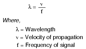
Calculating Wavelength
The wavelength (λ) of a signal is the distance a wave travels in one full cycle:
λ = v / f
where v is the propagation velocity and f is the frequency. In free space, v is the speed of light (≈186,000 mi/s). In coaxial cables, the velocity factor (usually < 1) reduces v.
For a 60 Hz power system, the wavelength is:
v = 186,000 mi/s × 0.66 ≈ 122,760 mi/s
f = 60 Hz
λ = 122,760 / 60 ≈ 2,046 mi
Thus a power line would need to be longer than 775 mi to be electrically long at 60 Hz. Similarly, a 10 kHz audio signal would require a cable longer than 4.65 mi before reflections become significant.
At radio frequencies the numbers shrink dramatically. A 100 MHz signal has a wavelength of about 9.82 ft (assuming full speed of light). A line longer than roughly 2.5 ft becomes electrically long, and with a velocity factor of 0.66 the threshold drops to 1.62 ft.
Effects of Short Transmission Lines
When the line is electrically short, the load’s impedance dominates the circuit. The line’s characteristic impedance has little effect beyond a very brief transient.
With an ohmmeter, a short coax cable appears as an open circuit because the meter’s measurement time far exceeds the round‑trip delay. The transient 50 Ω resistance that exists for a few microseconds is never detected.
In DC or slowly varying signals, virtually any cable length is electrically short. The same cable can behave very differently at high frequency, where propagation delays become comparable to the signal period.
Effects of Long Transmission Lines
When a line is electrically long, its characteristic impedance dominates. The load’s impedance becomes largely irrelevant because the wave never reaches it.
Consider an ideal infinite 50 Ω cable. Regardless of the load attached, a source at the other end will always see 50 Ω, because the signal never propagates to the load.
Mitigating Length Effects
The most reliable way to eliminate the influence of line length is to match the line’s characteristic impedance to the load. Perfect matching means the source always sees the same impedance, and reflections are eliminated.
In practice, exact matching may not be possible, but using impedance matching techniques—such as baluns, matching networks, or appropriate terminations—greatly reduces unwanted reflections and preserves signal integrity.
Key Takeaways
- Coaxial cables provide excellent noise immunity in both low‑frequency and high‑frequency circuits.
- An electrically short line has a propagation delay much smaller than the signal period; an electrically long line has a delay comparable to or exceeding a quarter cycle.
- The wavelength of a signal is λ = v/f; use this to determine whether a given line length is short or long.
- In short lines, the load impedance dominates; in long lines, the line’s characteristic impedance dominates.
- Matching the line to the load eliminates reflections and makes line length irrelevant to circuit behavior.
For more detailed analysis, see the Analog Devices article on transmission lines.
Industrial Technology
- Input & Output Coupling Techniques for Amplifiers: Capacitive, Direct, and Transformer Methods
- Analog and Digital Signals: Foundations of Industrial Instrumentation
- Finite-Length Transmission Lines: Impedance, Reflections, and Termination
- Transmission Fluid Explained: Purpose, Importance, and Maintenance Guide
- Bosch Pioneers Industry 4.0: Smartwatch‑Enabled Assembly Lines Boost Efficiency
- Designing Energy Transmission Systems: Key Considerations & Constraints
- Build or Buy: Choosing Custom Production Lines or Turnkey Solutions for Your Facility
- Transformer Testing: Short-Circuit and Open-Circuit Procedures Explained
- Understanding Weld Lines in Plastic Parts: Causes, Defects, and Prevention Strategies
- Understanding PCB Transmission Lines: Design, Function, and Applications