


Series LC Resonance: Zero Impedance and Voltage Peaks Explained
When the inductive and capacitive reactances in a series LC circuit match, their impedances cancel, driving the total impedance toward zero. This phenomenon, known as series resonance, causes the circuit to behave like a short at the resonant frequency.
Below is a schematic of a simple series resonant circuit:
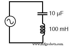
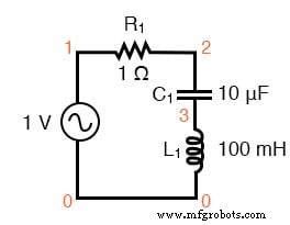
At the resonant frequency of 159.155 Hz, the total series impedance drops to 0 Ω, producing a short across the AC source—undesirable in many applications. To limit the peak current, a small series resistor is added, yielding a circuit suitable for SPICE simulation:
SPICE netlist:
series lc circuit
v1 1 0 ac 1 sin
r1 1 2 1
c1 2 3 10u
l1 3 0 100m
.ac lin 20 100 200
.plot ac i(v1)
.end
Simulation results show the current magnitude rising from left to right, peaking at 157.9 Hz—closest to the theoretical resonance of 159.155 Hz.
Including voltage plots for the capacitor and inductor reveals significant voltage spikes:
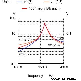
Here, the peak voltages across both the capacitor and inductor reach approximately 70 V, despite the source providing only 1 V. This stark contrast illustrates the high‑Q behavior of series resonant circuits.
Using the resonant frequency formula and component values:
Given: fr = 159.155 Hz, L = 100 mH, R = 1 Ω
XL = 2πfL = 100 Ω (j100)
XC = 1/(2πfC) = -j100 Ω
Z = R + j100 - j100 = 1 Ω
I = V/Z = 1 A
VL = I·XL = 100 V (j100)
VC = I·XC = -100 V (-j100)
VR = I·R = 1 V
Vtotal = VL + VC + VR = 1 V
Thus, the Q factor—ratio of component voltage to source voltage—is 100, indicating the potential for large component stresses even though the overall circuit voltage remains low.
Key Takeaways
- Series LC impedance approaches zero at resonance.
- The same resonant frequency formula applies to both series and parallel tanks.
- High currents can generate dangerously high voltages across individual components; careful component rating and safety practices are essential.
Related Worksheets
Industrial Technology
- Building and Troubleshooting a Basic 6‑V Battery‑Lamp Circuit
- Exploring Voltage Addition with Series Battery Connections
- Build a High‑Gain Differential Amplifier That Works as an Op‑Amp
- Key Rules for Series Circuits: Current, Resistance, and Voltage
- Understanding Simple Series Circuits: Key Principles and Practical Examples
- Parallel Circuits Explained: Voltage, Current, and Resistance Principles
- Understanding Series and Parallel Capacitors: How Capacitance Adds or Diminishes
- Fundamentals of AC Circuit Calculations: From Resistance to Kirchhoff’s Laws
- Parallel Tank Circuit Resonance: Theory, Calculations, and SPICE Verification
- Series A vs Series B Flanges: Key Differences & Applications