


Voltage Sensors: How They Work & Key Applications in Modern Power Systems
Voltage sensors are compact, high‑accuracy devices that convert electrical voltage into a measurable output—whether analog, digital, or audible. Their small footprint, safety, and reliability make them indispensable for monitoring AC or DC supplies in everything from industrial control systems to consumer electronics.
What Is a Voltage Sensor?
A voltage sensor measures the magnitude of an input voltage and translates it into a controlled output signal. Depending on the design, the output can be a switch, an analog voltage, a current, a pulse, or even a modulated signal (AM, PWM, FM). The sensor’s response is typically governed by a voltage divider or a sensing element such as a resistor or capacitor.
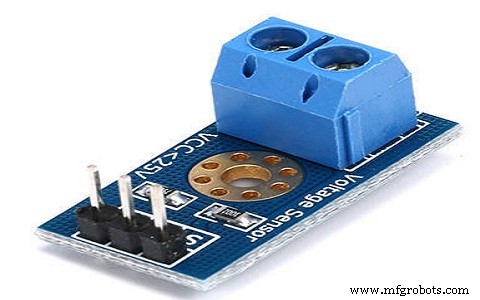
The device features two input pins—positive (+) and negative (−)—which connect to the circuit under test. The output typically includes a power supply pin (Vcc), a ground (GND) reference, and the sensing output (analog or digital).
Types of Voltage Sensors
Voltage sensors are broadly classified into two categories based on their sensing principle:
1) Resistive‑Type Sensor
Resistive sensors use a voltage divider or a bridge circuit. A precision resistor (or a variable resistor) divides the input voltage, and the resulting voltage drop is read as the output. In a bridge configuration, four resistors form a Wheatstone bridge; the unbalanced voltage is amplified to detect minute changes.
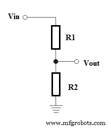
Mathematically, the output is calculated as:
Vout = (R1 / (R1 + R2)) × Vin
2) Capacitive‑Type Sensor
Capacitive sensors rely on a variable capacitance formed between two conductors separated by an insulator. When the sensor is powered (typically at 5 V), a small current flows, creating an electron distribution that changes with the applied voltage. The output is proportional to the capacitance ratio.
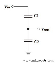
The relationship is:
Vout = (C1 / (C1 + C2)) × Vin
Applications
Voltage sensors enable a wide range of safety and performance functions, including:
- Detection of power failures and over‑voltage conditions
- Load monitoring and fault detection
- Safety switching and circuit protection
- Temperature‑controlled power management
- Dynamic load adjustment for energy efficiency
By providing real‑time voltage feedback, these devices help maintain system stability, protect equipment, and optimize energy usage.
Sensor
- How Distance Sensors Work and Their Key Applications
- Virtual Sensors: How They Work and Key Applications
- Lambda (Oxygen) Sensor: Function, Operation, and Key Automotive Applications
- Image Sensors: Types, Operation, and Practical Applications
- Gyroscope Sensors: How They Work and Their Key Applications
- Flame Sensors: How They Work and Key Applications in Fire Safety
- Sound Sensors: How They Work & Practical Applications
- Humidity Sensors: How They Work and Key Applications
- Rain Sensors Explained: How They Work & Key Applications
- Laser Sensors Explained: Working Principles & Industrial Applications