


Thevenin’s Theorem: Simplifying Linear Circuits for Power System Analysis
In electrical engineering, Thevenin’s Theorem guarantees that any linear network—composed of resistors, inductors, capacitors, and ideal sources—can be collapsed into an equivalent circuit with a single voltage source in series with a resistance. This reduction is invaluable when evaluating the effect of a single load resistor, especially in power‑distribution systems where load values frequently change.
Thevenin’s Theorem in Power Systems
Power systems routinely adjust load resistances as devices are switched on or off. Re‑solving a full network for each new load value using conventional methods (branch current, mesh current, Millman’s, or superposition) is time‑consuming. Thevenin’s Theorem removes that burden by transforming the entire network—excluding the load—into a simple series pair.
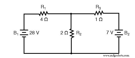
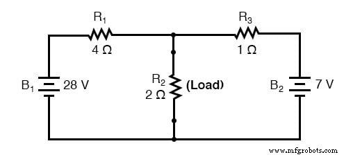
Assume R₂ is the load. We first isolate it, then reduce the remaining network to an equivalent voltage source EThevenin and series resistance RThevenin. The load is re‑connected to this pair, and the voltage and current across it follow directly from series‑circuit rules.
Thevenin Equivalent Circuit
After removal of R₂, the remaining elements (batteries B₁ and B₂, resistors R₁ and R₃) are represented by a single voltage source and a single resistance, as shown:
Once reduced:
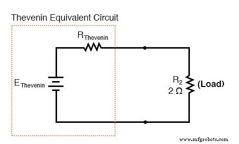
By construction, the load resistor cannot distinguish between the original network and its Thevenin equivalent; both deliver identical voltage and current for the same load value.
Determine Thevenin Voltage
With the load removed, compute the open‑circuit voltage between the two terminals:
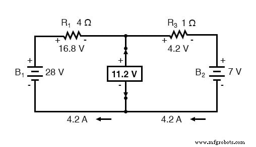
The result is EThevenin = 11.2 V.
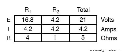
Determine Thevenin Series Resistance
Short all voltage sources (replace them with ideal wires) and open all current sources, then measure the resistance between the load terminals:
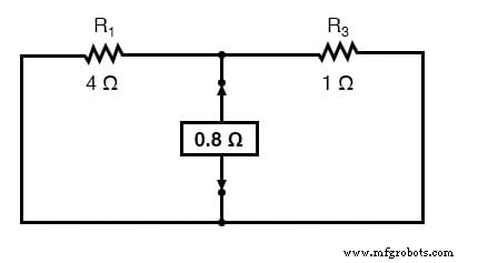
The two resistors are in parallel, yielding RThevenin = 0.8 Ω.
Compute Load Voltage and Current
Re‑attach the load (R₂ = 2 Ω) and analyze the simple series circuit:
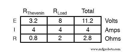
The load sees VR₂ = 8 V and IR₂ = 4 A, identical to values obtained via any detailed method.
Because the Thevenin equivalent is independent of the load, changing R₂ requires only a single recomputation using the same series‑circuit formulas.
Review
- Thevenin’s Theorem reduces any linear network to a single voltage source in series with a resistance.
- Procedure:
- Compute the open‑circuit voltage between the load terminals (EThevenin).
- Short all independent voltage sources and open all current sources; measure the resulting resistance between those terminals (RThevenin).
- Draw the equivalent circuit: EThevenin in series with RThevenin, then reconnect the load.
- Apply series‑circuit rules to find load voltage and current.
Related Worksheet
- Thevenin’s, Norton’s, and Maximum Power Transfer Theorems Worksheet
Industrial Technology
- Circuit With a Switch: A Practical Guide to Basic Electrical Circuits
- Voltage Follower Amplifier: Design, Build, and Measurement Guide
- Mastering AC Circuit Equations: Impedance, Reactance & Resonance
- Getting Started with SPICE: A Text‑Based Circuit Simulation Tool
- Mastering SPICE Netlist Syntax: Component Naming, Passive & Active Elements, and Source Definitions
- Thevenin’s Theorem: Simplifying Linear Circuits for Power System Analysis
- Millman's Theorem Explained: From Thevenin to Norton and the Millman Equation
- Master Thevenin’s Theorem: Step‑by‑Step Guide & Worked Example
- Master the Superposition Theorem: Step‑by‑Step Circuit Analysis with Practical Example
- Accurately Determining Circuit Breaker Count for Residential Panel Boards