


CMOS 555 Long‑Duration Blue LED Flasher – Practical 555 Astable Circuit Tutorial
Components & Materials
- 2 × AAA batteries
- Battery clip (Radio Shack #270‑398B)
- U1 – 1 CMOS TLC555 timer IC (Radio Shack #276‑1718 or equivalent)
- Q1 – 2N3906 PNP transistor (Radio Shack #276‑1604 or equivalent)
- Q2 – 2N2222 NPN transistor (Radio Shack #276‑1617 or equivalent)
- CR1 – 1N914 diode (Radio Shack #276‑1122 or equivalent – see notes)
- D1 – Blue LED (Radio Shack #276‑311 or equivalent)
- R1 – 1.5 MΩ ¼ W 5 % resistor
- R2 – 47 kΩ ¼ W 5 % resistor
- R3 – 2.2 kΩ ¼ W 5 % resistor
- R4 – 620 Ω ¼ W 5 % resistor
- R5 – 82 Ω ¼ W 5 % resistor
- C1 – 1 µF tantalum capacitor (Radio Shack #272‑1025 or equivalent)
- C2 – 100 µF electrolytic capacitor (Radio Shack #272‑1028 or equivalent)
- C3 – 470 µF electrolytic capacitor (Radio Shack #272‑1030 or equivalent)
Cross‑References
- Lessons In Electric Circuits, Vol. 1, Ch. 16 – “Voltage and Current Calculations”
- Lessons In Electric Circuits, Vol. 1, Ch. 16 – “Solving for Unknown Time”
- Lessons In Electric Circuits, Vol. 3, Ch. 4 – “Bipolar Junction Transistors”
- Lessons In Electric Circuits, Vol. 3, Ch. 9 – “Electrostatic Discharge”
- Lessons In Electric Circuits, Vol. 4, Ch. 10 – “Multivibrators”
Learning Objectives
- Apply RC time‑constant principles in a real circuit
- Implement a 555 timer in an astable multivibrator configuration
- Understand duty cycle and its impact on LED pulsing
- Practice ESD‑sensitive component handling
- Use transistors to boost current gain and protect the IC
- Employ a capacitor to temporarily double voltage for a high‑Vf LED
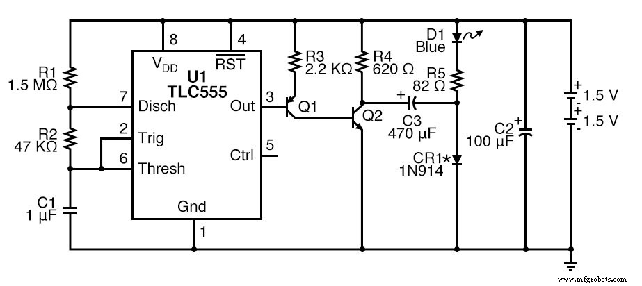
Schematic Diagram
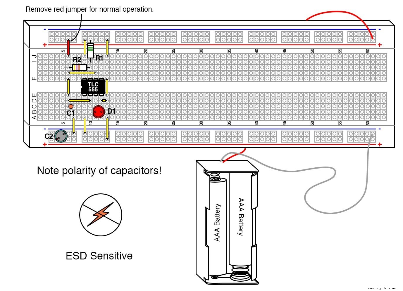
Illustration
Instructions
Because the CMOS 555 IC is highly sensitive to static discharge, protect it with a static‑discharge sleeve or a grounded grounding strap as described in Lessons In Electric Circuits, Vol. 3, Ch. 9.
Blue LEDs have a forward voltage of roughly 3.6 V, which exceeds the 3 V supplied by two AAA cells. The circuit uses a timing capacitor (C3) to momentarily boost the voltage, allowing the LED to flash for 30 ms pulses.
The design also works with a single 1.5 V cell. In that case, replace R5 with a 10 Ω resistor and use a red LED. The LM3909‑based prototype that inspired this board operated for over a year on a single D cell.
CR1’s role is simply to clamp the voltage; any silicon or Schottky diode will perform adequately. Lower‑drop diodes (e.g., Schottky) improve efficiency and LED brightness.
Theory of Operation
When Q2 is off, C3 charges to the battery voltage minus the diode drop, isolating the blue LED. Upon turning Q2 on, the negative side of C3 is pulled to –2.4 V, reversing the diode and allowing the stored energy to discharge through R5 and the LED, creating a 5.4 V pulse that illuminates the LED.
Because C3 discharges quickly, the LED is visible only during the brief pulse. Leakage current at 3 V may produce a faint glow when the LED is nominally off, a common real‑world observation.
Industrial Technology
- Using a Transistor as an Electrically Controlled Switch
- The 555 Integrated Circuit: A Timeless Benchmark in Analog Design
- 555 Hysteretic Oscillator – Build a Classic RC Multivibrator
- CMOS 555 LED Flasher – Long‑Duration, Low‑Power Red LED Pulsing Circuit
- CMOS 555 Long‑Duration Flyback LED Flasher
- CMOS 555 Long‑Duration Red LED Flasher – Precision Driver Circuit for Reliable Performance
- Crystal and Transistor Radio Circuits: From Basic Detectors to Integrated AM/FM Receivers
- LED Roulette Circuit Using 555 Timer & CD4017 Counter – Full Diagram & Build Guide
- LED Flasher Module Guide: Everything You Need to Know
- Master the 555 LED Flasher: A Comprehensive Guide