


CMOS 555 Long‑Duration Red LED Flasher – Precision Driver Circuit for Reliable Performance
Components & Materials
- 2 × AAA batteries (fresh alkaline recommended)
- Battery clip (Radio Shack #270‑398B)
- Digital multimeter or voltage‑only meter
- U1 – CMOS TLC555 timer IC (RS #276‑1718 or equivalent)
- Q1 – 2N3906 PNP transistor (RS #276‑1604 or equivalent)
- Q2 – 2N2222 NPN transistor (RS #276‑1617 or equivalent)
- D1 – Red LED (RS #276‑041 or equivalent)
- R1 – 1.5 MΩ, ¼ W, 5 % tolerance resistor
- R2 – 47 kΩ, ¼ W, 5 % tolerance resistor
- R3 – 2.2 kΩ, ¼ W, 5 % tolerance resistor
- R4 – 27 Ω, ¼ W, 5 % tolerance resistor (adjust for LED forward voltage)
- C1 – 1 µF tantalum capacitor (RS #272‑1025 or equivalent)
- C2 – 100 µF electrolytic capacitor (RS #272‑1028 or equivalent)
Cross‑References
- Lessons In Electric Circuits, Vol. 1, Chap. 16 – Voltage & Current Calculations
- Lessons In Electric Circuits, Vol. 1, Chap. 16 – Solving for Unknown Time
- Lessons In Electric Circuits, Vol. 3, Chap. 4 – Bipolar Junction Transistors
- Lessons In Electric Circuits, Vol. 3, Chap. 9 – Electrostatic Discharge
- Lessons In Electric Circuits, Vol. 4, Chap. 10 – Multivibrators
Learning Objectives
- Apply RC time‑constant concepts in a real circuit
- Explore an Astable 555 timer configuration
- Understand and calculate duty cycle
- Implement ESD protection for sensitive CMOS devices
- Use transistors to boost current capability
- Calculate proper LED series resistance
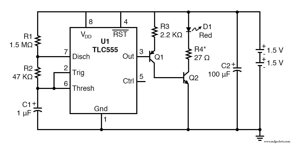
Schematic Diagram
Illustration
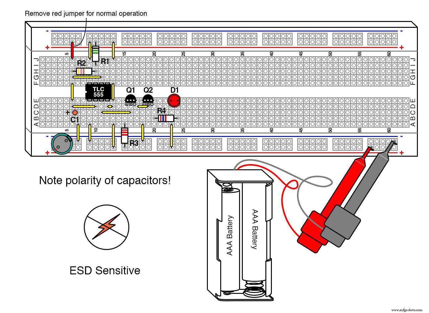
Instructions
ESD Precautions
Because the TLC555 is highly sensitive to static, follow the guidelines in Lessons In Electric Circuits, Vol. 3, Chap. 9. Use anti‑static wrist straps or work on a grounded mat.
This design builds on the earlier “Long‑Duration Minimum‑Parts Red LED Flasher” by adding transistor drivers that keep the LED current steady even as the battery voltage falls.
Q1 and Q2 form a low‑load, high‑gain driver that preserves the TLC555’s output drive. As the battery voltage dips toward 2 V, the driver still supplies enough current to saturate Q2, ensuring the LED stays fully lit during its on‑phase.
Because LED forward voltage (VF) varies, R4 must be chosen to maintain a target of ~20 mA. For example:
- VF = 2.5 V → R4 ≈ 27 Ω (18.5 mA)
- VF = 2.1 V → R4 ≈ 47 Ω (20 mA)
- VF = 1.5 V → R4 ≈ 75 Ω (20 mA)
Measure VF with the LED on full‑time (use the jumper shown in red) and compute R4 using:
R4 = (3 V – VF) / 0.02 A
Replacing C2 (100 µF) will temporarily reduce battery life; the LED will dim after a week or two but will recover within seconds once the capacitor is restored. With fresh AAA cells, this flasher can run uninterrupted for up to three months.
Theory of Operation
The transistor driver employs a common‑collector stage (Q1) followed by a common‑emitter stage (Q2). This configuration offers:
- Very high input resistance (≥ 100 kΩ) so the TLC555 sees a minimal load.
- Strong drive to saturate Q2, turning the LED on fully during each cycle.
Q1’s β (≈ 50 minimum) multiplies the emitter resistor, ensuring the driver loads the 555 IC negligibly. Even with gain variations across the same transistor family, the design remains robust. When Q1 turns on, it forwards about 1 mA to Q2, which is sufficient to saturate Q2 and switch the LED on.
Industrial Technology
- Using a Transistor as an Electrically Controlled Switch
- Pulsed‑Light Sensor: Amplify LED Light Pulses into Audible Sound
- Build an LED Sequencer with 555 Timer & 4017 Counter – Frequency Division & Debounce
- The 555 Integrated Circuit: A Timeless Benchmark in Analog Design
- CMOS 555 LED Flasher – Long‑Duration, Low‑Power Red LED Pulsing Circuit
- CMOS 555 Long‑Duration Blue LED Flasher – Practical 555 Astable Circuit Tutorial
- CMOS 555 Long‑Duration Flyback LED Flasher
- LED Roulette Circuit Using 555 Timer & CD4017 Counter – Full Diagram & Build Guide
- LED Flasher Module Guide: Everything You Need to Know
- Master the 555 LED Flasher: A Comprehensive Guide