


CMOS 555 Long‑Duration Flyback LED Flasher
Parts & Materials
- Two AAA Batteries
- Battery Clip (Radio Shack catalog # 270-398B)
- U1, U2 – CMOS TLC555 timer IC (Radio Shack catalog # 276-1718 or equivalent)
- Q1 – 2N3906 PNP Transistor (Radio Shack catalog # 276-1604 (15 pack) or equivalent)
- Q2 – 2N2222 NPN Transistor (Radio Shack catalog # 276-1617 (15 pack) or equivalent)
- D1 – Red LED (Radio Shack catalog # 276-041 or equivalent)
- D2 – Blue LED (Radio Shack catalog # 276-311 or equivalent)
- R1 – 1.5 MΩ 1/4W 5% Resistor
- R2 – 47 kΩ 1/4W 5% Resistor
- R3, R5 – 10 kΩ 1/4W 5% Resistor
- R4 – 1 MΩ 1/4W 5% Resistor
- R6 – 100 kΩ 1/4W 5% Resistor
- R7 – 1 kΩ 1/4W 5% Resistor
- C1 – 1 µF Tantalum Capacitor (Radio Shack catalog # 272-1025 or equivalent)
- C2 – 100 pF Ceramic Disc Capacitor (Radio Shack catalog # 272-123)
- C3 – 100 µF Electrolytic Capacitor (Radio Shack catalog # 272-1028 or equivalent)
- L1 – 200 µH Choke or Inductor (Exact value not critical, see end of chapter)
Cross‑References
- Lessons In Electric Circuits, Volume 1, chapter 16: “Inductor transient response”
- Lessons In Electric Circuits, Volume 1, chapter 16: “Why L/R and not LR?”
- Lessons In Electric Circuits, Volume 3, chapter 4: “The common‑emitter amplifier”
- Lessons In Electric Circuits, Volume 3, chapter 9: “Electrostatic Discharge”
- Lessons In Electric Circuits, Volume 4, chapter 10: “Monostable multivibrators”
Learning Objectives
- Explore a less‑common operating mode of the 555 timer
- Apply proper electrostatic discharge (ESD) handling techniques
- Use a transistor as a simple inverter gate (resistor‑transistor logic)
- Harness inductive flyback to step‑up voltage for LED lighting
- Construct a custom inductor from readily available materials
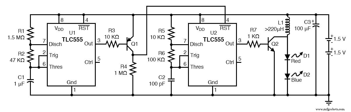
Schematic Diagram
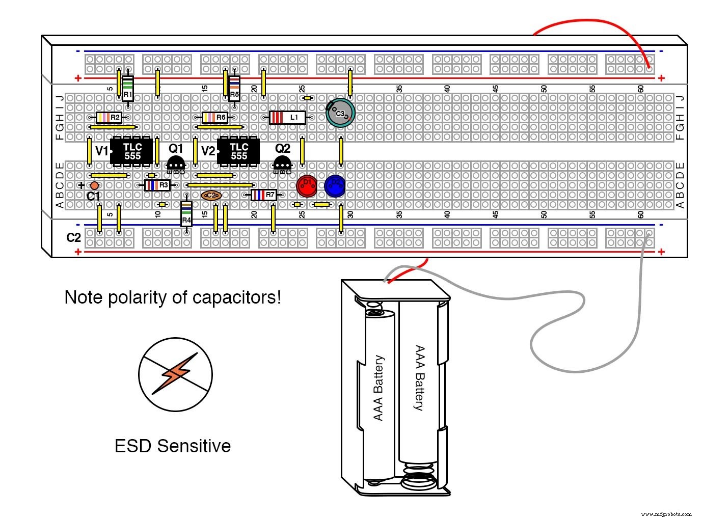
Illustration
Instructions
NOTE: The CMOS 555 is highly sensitive to electrostatic discharge. Follow the protection guidelines in Volume 3, Chapter 9, “Electrostatic Discharge” to avoid damaging the IC.
This experiment builds on the “Commutating diode” (Volume 6, chapter 5). Review that section before proceeding.
We use a CMOS 555 to flash an LED while boosting the battery voltage with an inductive flyback, mirroring the principle of a Joule Thief. Although the 555 is rated for a minimum of 2 V, the circuit can run on 1.5 V batteries thanks to the high‑efficiency energy conversion.
The design can drive multiple LEDs in series; as the count rises, battery life decreases because the inductor’s peak voltage depends on supply voltage. In this example, two different LEDs demonstrate the circuit’s independence from individual LED voltage drops. The blue LED dominates the perceived brightness, yet the red LED reaches its maximum intensity.
Careful LED polarity is essential. A mis‑oriented blue LED, which is more ESD‑sensitive, will likely be destroyed by the inductive pulse. Likewise, the transistor and the 555 IC can be damaged by uncontrolled spikes.
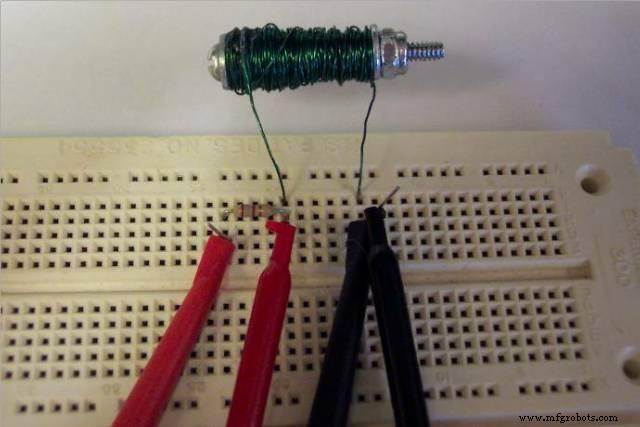
The inductor is the most forgiving component. It can be a standard choke, a solenoid coil, or even a relay coil. Below is a step‑by‑step guide to build a 220 µH coil using 26 AWG magnet wire.
Parts & Materials for Coil
- 26 ft (8 m) of 26 AWG magnet wire (Radio Shack catalog # 278-1345 or equivalent)
- 6/32×1.5‑inch screw, M4×30 mm screw, or a similarly sized steel or iron nail (not stainless)
- Optional lock nut
- Optional transparent tape (if using screws)
- Super glue
- Soldering iron & solder
Coils are not precision components; their inductance can vary. Aim for ≥220 µH. The construction steps below are straightforward and reproducible.
1. Wrap the wire around the screw or nail in a single tight layer, keeping the coil length to 1 in (25 mm). Secure the start of the coil with a thin strip of transparent tape or a tacked‑on glue dot.
2. Apply a small amount of super glue at the screw head to lock the first layer in place. Allow the glue to set before adding subsequent turns.
3. Continue winding, applying glue as needed to maintain tension and shape, until the wire is almost fully wound. Leave a 1‑in section of wire free for the second lead.
4. Strip the enamel from the ends of the two leads, tin them with solder, and you now have a functional inductor.
5. Measure the inductance with a multimeter or LCR meter; typical values fall close to 220 µH.
Figures below illustrate the finished coil and the measurement setup.
Industrial Technology
- Using a Transistor as an Electrically Controlled Switch
- Pulsed‑Light Sensor: Amplify LED Light Pulses into Audible Sound
- Build an LED Sequencer with 555 Timer & 4017 Counter – Frequency Division & Debounce
- The 555 Integrated Circuit: A Timeless Benchmark in Analog Design
- CMOS 555 LED Flasher – Long‑Duration, Low‑Power Red LED Pulsing Circuit
- CMOS 555 Long‑Duration Blue LED Flasher – Practical 555 Astable Circuit Tutorial
- CMOS 555 Long‑Duration Red LED Flasher – Precision Driver Circuit for Reliable Performance
- LED Roulette Circuit Using 555 Timer & CD4017 Counter – Full Diagram & Build Guide
- LED Flasher Module Guide: Everything You Need to Know
- Master the 555 LED Flasher: A Comprehensive Guide