


Designing an FPGA‑Based RC Servo Controller with Precise PWM
Radio‑controlled (RC) servos are the heart of hobbyist aircraft, cars, and boats. They translate a remote radio command into a precise angular position. Because RC systems have been around for decades, the industry‑standard interface is pulse‑width modulation (PWM) rather than a pure digital protocol. With the deterministic timing that a field‑programmable gate array (FPGA) offers, implementing high‑precision PWM is straightforward. This article walks through a generic VHDL servo controller that works with any RC servo using PWM, including a simulation testbench and a real‑world implementation on a Lattice iCEstick FPGA board.
How PWM Control for an RC Servo Works
While PWM fundamentals are covered elsewhere, RC servos require a slightly different approach. The servo ignores the full duty cycle; it samples only the duration of the high period of each pulse. The standard interval between pulses is 20 ms, which corresponds to a 50 Hz frequency. Within that 20 ms window the servo reads a pulse whose width typically ranges from 1 ms (minimum position) to 2 ms (maximum position), though exact values vary by manufacturer.
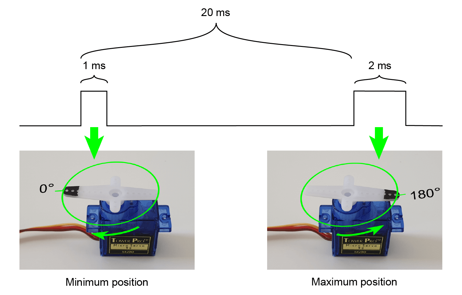
The figure illustrates the timing relationship: a 20 ms period repeats, and the high time of each pulse directly maps to the servo’s angular position.
The VHDL Servo Controller
We’ll build a generic VHDL module that accepts generic parameters for clock frequency, PWM pulse frequency, minimum and maximum pulse widths (in microseconds), and the number of discrete positions between the extremes. Because the FPGA clock runs in the megahertz range, integer counter arithmetic gives us sufficient resolution. To avoid rounding ambiguities, we’ll use the round function from the ieee.math_real package, which always rounds away from zero.
library ieee;
use ieee.std_logic_1164.all;
use ieee.numeric_std.all;
use ieee.math_real.round;
Below is the entity declaration for the servo module:
entity servo is
  generic (
    clk_hz : real;
    pulse_hz : real; -- PWM pulse frequency
    min_pulse_us : real; -- microseconds at minimum position
    max_pulse_us : real; -- microseconds at maximum position
    step_count : positive -- Number of discrete positions
  );
  port (
    clk : in std_logic;
    rst : in std_logic;
    position : in integer range 0 to step_count - 1;
    pwm : out std_logic
  );
end servo;
The position input drives the servo from its minimum (0) to maximum (step_count‑1) setting. The pwm output connects to the servo’s signal wire (usually yellow or white). Most FPGAs output 3.3 V logic, so a level shifter is required to match the servo’s 5 V input.
The Declarative Region
We begin by defining a helper function that converts a time in microseconds to the nearest integer number of clock cycles:
function cycles_per_us (us_count : real) return integer is
begin
  return integer(round(clk_hz / 1.0e6 * us_count));
end function;
Using that function, we calculate the core timing constants:
constant min_count : integer := cycles_per_us(min_pulse_us);
constant max_count : integer := cycles_per_us(max_pulse_us);
constant min_max_range_us : real := max_pulse_us - min_pulse_us;
constant step_us : real := min_max_range_us / real(step_count - 1);
constant cycles_per_step : positive := cycles_per_us(step_us);
Next, we set up the PWM counter that runs at the desired pulse frequency:
constant counter_max : integer := integer(round(clk_hz / pulse_hz)) - 1;
signal counter : integer range 0 to counter_max;

signal duty_cycle : integer range 0 to max_count;
Counting Clock Cycles
The following process implements the free‑running counter:
COUNTER_PROC : process(clk)
begin
  if rising_edge(clk) then
    if rst = '1' then
      counter <= 0;
    else
      if counter < counter_max then
        counter <= counter + 1;
      else
        counter <= 0;
      end if;
    end if;
  end if;
end process;
PWM Output Process
The PWM output is driven high for as many counter cycles as the current duty_cycle value dictates:
PWM_PROC : process(clk)
begin
  if rising_edge(clk) then
    if rst = '1' then
      pwm <= '0';
    else
      pwm <= '0';
      if counter < duty_cycle then
        pwm <= '1';
      end if;
    end if;
  end if;
end process;
Calculating the Duty Cycle
When reset, duty_cycle defaults to the minimum pulse width. Otherwise, it is computed from the position input:
DUTY_CYCLE_PROC : process(clk)
begin
  if rising_edge(clk) then
    if rst = '1' then
      duty_cycle <= min_count;
    else
      duty_cycle <= position * cycles_per_step + min_count;
    end if;
  end if;
end process;
Although cycles_per_step is rounded to the nearest integer, the resulting error is negligible because the FPGA clock is orders of magnitude faster than the 50 Hz pulse rate.
The Servo Testbench
To verify the design, we built a simple testbench that manually steps through all position values and captures the waveform. A 1 MHz test clock speeds up simulation while still reflecting realistic timing.
Simulation Constants
constant clk_hz : real := 1.0e6;
constant clk_period : time := 1 sec / clk_hz;

constant pulse_hz : real := 50.0;
constant pulse_period : time := 1 sec / pulse_hz;
constant min_pulse_us : real := 1000.0;
constant max_pulse_us : real := 2000.0;
constant step_count : positive := 5;
DUT Signals
signal clk : std_logic := '1';
signal rst : std_logic := '1';
signal position : integer range 0 to step_count - 1;
signal pwm : std_logic;
Clock generation:
clk <= not clk after clk_period / 2;
DUT Instantiation
DUT : entity work.servo(rtl)
generic map (
  clk_hz => clk_hz,
  pulse_hz => pulse_hz,
  min_pulse_us => min_pulse_us,
  max_pulse_us => max_pulse_us,
  step_count => step_count
)
port map (
  clk => clk,
  rst => rst,
  position => position,
  pwm => pwm
);
Testbench Sequencer
The sequencer resets the DUT, then iterates through all position values, waiting one pulse period between changes. After completing the sequence, the simulation ends.
SEQUENCER : process
begin
  wait for 10 * clk_period;
  rst <= '0';

  wait for pulse_period;

  for i in 0 to step_count - 1 loop
    position <= i;
    wait for pulse_period;
  end loop;

  report "Simulation done. Check waveform.";
  finish;
end process;
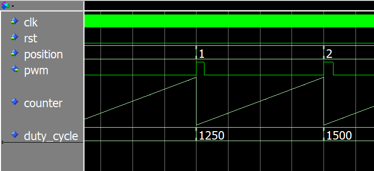
Servo Simulation Waveform
The following snapshot shows the testbench waveform. The PWM output is high only for the earliest counter cycles, matching the expected pulse width for each position value.
Download the full project files to reproduce the simulation.
Example FPGA Implementation
Next, we drive a real TowerPro SG90 servo from a Lattice iCEstick board. The servo requires a 5 V logic level, so we use a level shifter between the FPGA pin and the servo’s signal wire.
Top Module Entity
entity top is
  port (
    clk : in std_logic;
    rst_n : in std_logic; -- Pull‑up
    pwm : out std_logic
  );
end top;
Signals and Constants
We calibrated the servo pulse widths experimentally: 0.5 ms to 2.5 ms yields a full 180° sweep. The following constants match the iCEstick clock and servo parameters.
constant clk_hz : real := 12.0e6; -- iCEstick clock
constant pulse_hz : real := 50.0;
constant min_pulse_us : real := 500.0; -- 0.5 ms
constant max_pulse_us : real := 2500.0; -- 2.5 ms
constant step_bits : positive := 8; -- 0 to 255
constant step_count : positive := 2**step_bits;
The free‑running counter is 25 bits wide, giving a wrap time of roughly 2.8 seconds on the 12 MHz clock.
constant cnt_bits : integer := 25;
signal cnt : unsigned(cnt_bits - 1 downto 0);
Connecting the modules:
signal rst : std_logic;
signal position : integer range 0 to step_count - 1;
signal rom_addr : unsigned(step_bits - 1 downto 0);
signal rom_data : unsigned(step_bits - 1 downto 0);
Servo Module Instantiation
SERVO : entity work.servo(rtl)
generic map (
  clk_hz => clk_hz,
  pulse_hz => pulse_hz,
  min_pulse_us => min_pulse_us,
  max_pulse_us => max_pulse_us,
  step_count => step_count
)
port map (
  clk => clk,
  rst => rst,
  position => position,
  pwm => pwm
);
Self‑Wrapping Counter Instantiation
COUNTER : entity work.counter(rtl)
generic map (
  counter_bits => cnt_bits
)
port map (
  clk => clk,
  rst => rst,
  count_enable => '1',
  counter => cnt
);
Sine ROM Instantiation
SINE_ROM : entity work.sine_rom(rtl)
generic map (
  data_bits => step_bits,
  addr_bits => step_bits
)
port map (
  clk => clk,
  addr => rom_addr,
  data => rom_data
);
Concurrent assignments wire the counter, ROM, and servo together:
position <= to_integer(rom_data);
rom_addr <= cnt(cnt'left downto cnt'left - step_bits + 1);
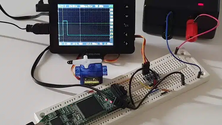
Testing on the Lattice iCEstick
The entire circuit is breadboarded: the FPGA’s 3.3 V output is level‑shifted to 5 V for the servo. The PWM signal connects to pin 119 on the iCEstick. When powered, the servo oscillates smoothly between 0° and 180°, pausing briefly at the extremes. A video of the PWM waveform on an oscilloscope demonstrates the correct timing.
Final Thoughts
There are many ways to implement a PWM servo controller in VHDL, but using integer counters keeps the synthesized logic simple—only counters, registers, and multiplexers. The most common pitfall is silent overflow in 32‑bit arithmetic, so always verify that intermediate calculations stay within bounds for your chosen parameters.
Note that this PWM style is tailored for RC servos. For applications where the duty cycle matters more than the frequency (e.g., analog power control), a different PWM strategy is preferable.
Read about analog power control using PWM here:
How to create a PWM controller in VHDL
Ready to try it yourself? Download the ZIP archive containing the complete VHDL code, ModelSim testbench, iCEcube2 project, and programmer configuration by entering your email address below.
Let me know what you think in the comments!
VHDL
- PWM Power Controller: Build a Pulse‑Width Modulated Lamp Driver
- Implementing a PWM Controller in VHDL: Design, Simulation, and FPGA Demo
- Initializing FPGA Block RAM from Text Files Using VHDL’s TEXTIO Library
- Monitor Your Home Temperature with a Raspberry Pi Dashboard
- Can Your Servo Controllers Be Repaired? Expert Insights & Cost-Effective Solutions
- Real‑Time Heartbeat LED Visualizer Powered by ECG
- Smart IR-Activated Water Tap Controlled by Arduino UNO – Efficient & Eco-Friendly
- Arduino‑Powered Robot Arm with Custom Controller – Servo & Potentiometer Build
- 555 Timer PWM DC Motor Speed Controller – Build & PCB Design Guide
- Tel Aviv University Robot Uses Locust Ear to Hear and Respond to Sound