


Creating a Tcl-Driven Testbench for a VHDL Code‑Lock Module
Most VHDL simulators expose the Tool Command Language (Tcl) as their primary scripting interface. When you type a command at the simulator console, you are using Tcl, and you can also write scripts that drive and observe your VHDL design.
This article walks you through building a self‑checking testbench that uses Tcl—rather than VHDL—to verify the behavior of a simple code‑lock module. The result is a clear, maintainable test harness that can be run, modified, and reused without recompiling the VHDL.
See also:
Download the code and ModelSim project files below.
The DUT: A Code‑Lock Module in VHDL
Before we dive into the testbench, let’s review the Device Under Test (DUT). The module emulates a simple lock that opens a vault when the correct numeric sequence is entered on a PIN pad.
Although many people refer to such a device as a "combination lock," the correct term is a "permutation lock"—the order of the digits matters. For clarity, we’ll call it a code lock throughout.
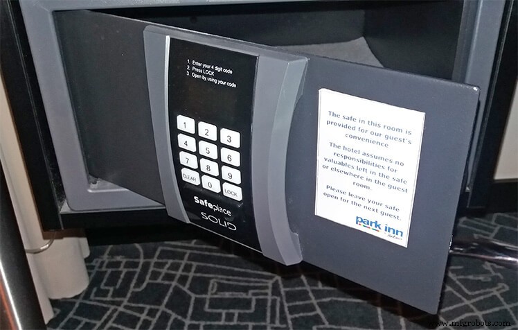
The illustration above shows a typical hotel safe. For simplicity, our design uses only numeric keys and omits the CLEAR and LOCK buttons.
How the Code Lock Module Works
The lock starts in a locked state. When a user enters four consecutive digits that match the secret PIN, the lock opens. Entering an incorrect sequence relocks the device. This behavior is implemented as a simple sequence detector in VHDL.

The waveform illustrates the timing of the module. In addition to the clock and reset, the module accepts two inputs: input_digit (an integer 0–9) and input_enable (a std_logic). The DUT samples the digit on a rising clock edge when enable is high.
The only output is unlock, a std_logic that goes high only when the four consecutive digits match the correct PIN. In this example, the passcode is 1234.
The Entity
The following entity definition hard‑codes the secret PIN via generics. Each generic is an integer in the range 0–9, representing a Binary Coded Decimal (BCD) digit.
entity code_lock is
  generic (pin0, pin1, pin2, pin3 : integer range 0 to 9);
  port (
    clk : in std_logic;
    rst : in std_logic;
    input_digit : in integer range 0 to 9;
    input_enable : in std_logic;
    unlock : out std_logic
  );
end code_lock;
The Declarative Region
The module uses a single internal signal—a 4‑bit shift register that stores the most recent digits entered. We allow the register to hold values from –1 to 9. The special value –1 is used for the reset state, ensuring that a PIN of 0000 does not unlock the lock by default.
type pins_type is array (0 to 3) of integer range -1 to 9;
signal pins : pins_type;
The Implementation
The architecture includes a combinational assignment that drives unlock high when the shift register matches the generic PIN values. Because pins is clocked, unlock changes only on a rising clock edge.
unlock <= '1' when pins = (pin3, pin2, pin1, pin0) else '0';
The following process implements the shift register. On reset, all entries are set to –1. When input_enable is high on a rising edge, the current digit is stored in position 0, and the previous digits shift right.
PINS_PROC : process(clk)
begin
  if rising_edge(clk) then
    if rst = '1' then
      pins <= (others => -1);
    else
      if input_enable = '1' then
        pins(0) <= input_digit;
        pins(1 to 3) <= pins(0 to 2);
      end if;
    end if;
  end if;
end process;
The VHDL Testbench
Even though we’ll use Tcl for the verification logic, we still need a basic VHDL testbench to generate the clock and reset signals. Below is the complete VHDL testbench file.
library ieee;
use ieee.std_logic_1164.all;

entity code_lock_tb is
end code_lock_tb;

architecture sim of code_lock_tb is

  constant clk_hz : integer := 100e6;
  constant clock_period : time := 1 sec / clk_hz;

  signal clk : std_logic := '1';
  signal rst : std_logic := '1';
  signal input_digit : integer range 0 to 9;
  signal input_enable : std_logic := '0';
  signal unlock : std_logic;

begin

  clk <= not clk after clock_period;

  DUT : entity work.code_lock(rtl)
    generic map (1,2,3,4)
    port map (
      clk => clk,
      rst => rst,
      input_digit => input_digit,
      input_enable => input_enable,
      unlock => unlock
    );

end architecture;
The Tcl Testbench
Below is a Tcl script that runs inside ModelSim. If you use Vivado or another simulator, minor adjustments will be required, as some commands are simulator‑specific. Refer to the ModelSim Command Reference Manual for details.
Download the example project using the form below.
Using a Namespace
Encapsulating the script in a namespace prevents accidental clashes with global variables. All Tcl code resides inside the codelocktb namespace.
namespace eval ::codelocktb {
  # All Tcl code here
}
Initializing the Simulation
We start the simulation with vsim and load the waveform file if it exists.
# Load the simulation
vsim work.code_lock_tb

# Load the waveform
if {[file exists wave.do]} {
  do wave.do
}
Importing VHDL Values into Tcl
Using ModelSim’s examine command, we read the clock_period constant and the PIN generics. The following snippet extracts the numeric value and time unit.
variable clockPeriod [examine clock_period]
variable clockPeriod [string trim $clockPeriod "{}"]
variable timeUnits [lindex $clockPeriod 1]
variable clockPeriod [lindex $clockPeriod 0]
variable pinCode [examine dut.pin0 dut.pin1 dut.pin2 dut.pin3]
We also initialise an errorCount variable to track failures.
variable errorCount 0
Printing with a Timestamp
The echo command displays messages in the ModelSim console on all platforms. The following procedure prefixes each message with the current simulation time.
proc printMsg { msg } {
  global now
  variable timeUnits
  echo $now $timeUnits: $msg
}
Running for a Specified Number of Clock Cycles
Because the DUT is clock‑sensitive, we advance time in multiples of the clock period.
proc runClockCycles { count } {
  variable clockPeriod
  variable timeUnits
  set t [expr {$clockPeriod * $count}]
  run $t $timeUnits
}
Checking Signal Values
The checkSignal procedure compares a VHDL signal against an expected value, reporting an error if they differ.
proc checkSignal { signalName expectedVal } {
  variable errorCount
  set val [examine $signalName]
  if {$val != $expectedVal} {
    printMsg "ERROR: $signalName=$val (expected=$expectedVal)"
    incr errorCount
  }
}
Simulating PIN Entry
This procedure drives the DUT inputs to simulate a user entering a 4‑digit PIN. It checks the unlock output once all four digits have been applied.
proc tryPin { digits } {
  variable pinCode
  set pinStatus "incorrect"
  if { $digits == $pinCode } { set pinStatus "correct" }
  printMsg "Entering $pinStatus PIN code: $digits"
  foreach i $digits {
    force input_digit $i -deposit
    force input_enable 1 -deposit
    runClockCycles 1
    force input_enable 0 -deposit
    runClockCycles 1
  }
  if { $pinStatus == "correct" } {
    checkSignal unlock 1
  } else {
    checkSignal unlock 0
  }
}
Test Sequence and Result Reporting
After a brief initialization period, the script releases reset and runs several test cases: two corner cases (0000 and 9999), the correct PIN, and the reversed PIN sequence. It then reports the overall result.
runClockCycles 10
force rst '0' -deposit
runClockCycles 1
printMsg "Checking reset value"
checkSignal unlock 0
tryPin {0 0 0 0}
tryPin {9 9 9 9}
tryPin $pinCode
tryPin [lreverse $pinCode]
if { $errorCount == 0 } {
  printMsg "Test: OK"
} else {
  printMsg "Test: Failure ($errorCount errors)"
}
Running the Testbench
Execute the script with the following command inside ModelSim:
source code_lock/code_lock_tb.tcl
A successful run produces output similar to the following, with timestamps preceding each message.
VSIM> source code_lock/code_lock_tb.tcl
# vsim
# 110 ns: Checking reset value
# 110 ns: Entering incorrect PIN code: 0 0 0 0
# 190 ns: Entering incorrect PIN code: 9 9 9 9
# 270 ns: Entering correct PIN code: 1 2 3 4
# 350 ns: Entering incorrect PIN code: 4 3 2 1
# 430 ns: Test: OK
If the DUT contains a defect (e.g., a typo in the unlock assignment), the script reports the failure and the error count.
VSIM> source code_lock/code_lock_tb.tcl
# vsim
# 110 ns: Checking reset value
# 110 ns: Entering incorrect PIN code: 0 0 0 0
# 190 ns: Entering incorrect PIN code: 9 9 9 9
# 270 ns: Entering correct PIN code: 1 2 3 4
# 350 ns: ERROR: unlock=0 (expected=1)
# 350 ns: Entering incorrect PIN code: 4 3 2 1
# 430 ns: Test: Failure (1 errors)
Final Thoughts
Throughout my career, I’ve written numerous Tcl‑based testbenches. They offer unique advantages: interactive testing, the ability to modify the test harness without recompiling, and an extra layer of verification that guards against bugs in both the design and the testbench.
However, there are trade‑offs. Tcl scripts run noticeably slower than pure VHDL testbenches, and the language can be fragile—errors are hard to catch early, and debugging is less intuitive than in higher‑level languages like Python.
Despite these drawbacks, Tcl remains the de‑facto glue language for FPGA tooling and simulation. If you work with Xilinx Vivado, Intel Quartus, or Mentor Graphics Questa, mastering Tcl will pay dividends. Feel free to share your experiences in the comments below.
VHDL
- Creating String Lists in VHDL: Best Practices & Example
- Gracefully Ending a VHDL Testbench Simulation
- Implementing a PWM Controller in VHDL: Design, Simulation, and FPGA Demo
- How to Build a Self‑Checking Testbench in VHDL – A Practical Guide
- Implementing a Dynamic Linked List in VHDL with Protected Types and Access Pointers
- Designing a Finite‑State Machine in VHDL: A Practical Traffic Light Example
- Build a Reliable Timer in VHDL: Counting Clock Cycles to Hours
- Building a Clock‑Triggered Process in VHDL: A Practical Guide
- Mastering Concurrent Statements in VHDL: A Practical Guide
- Mastering std_logic_vector: Creating Signal Vectors in VHDL