


Mastering High‑Quality STL Export Settings for Precise 3D Printing
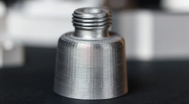
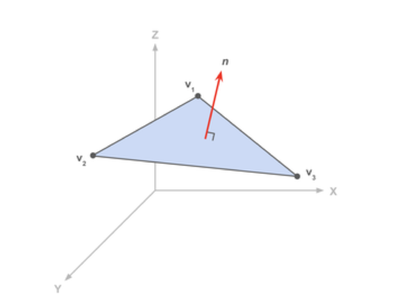
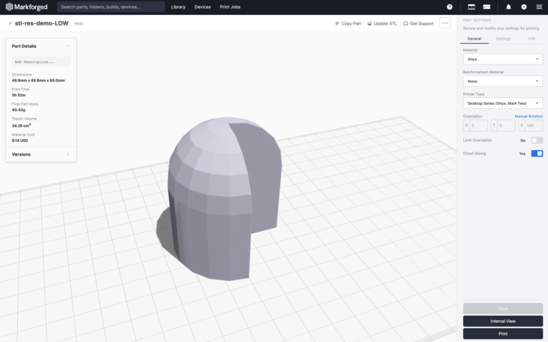
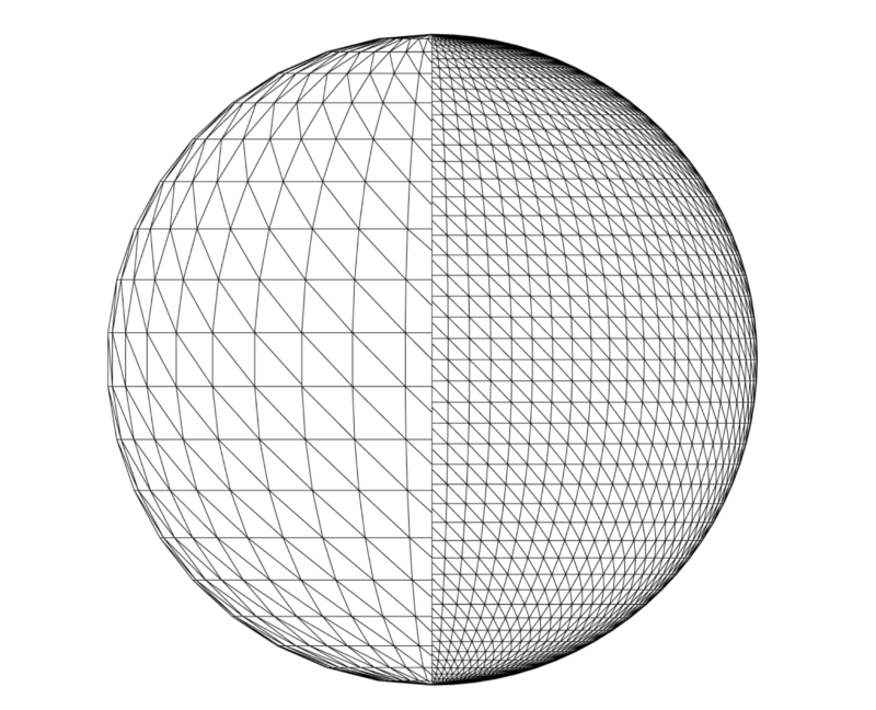
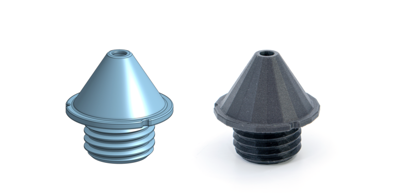
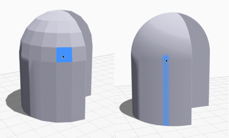
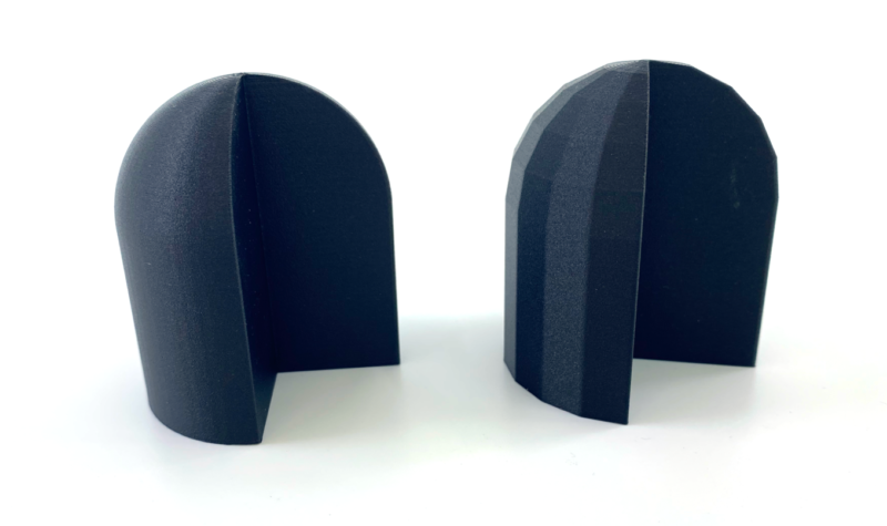
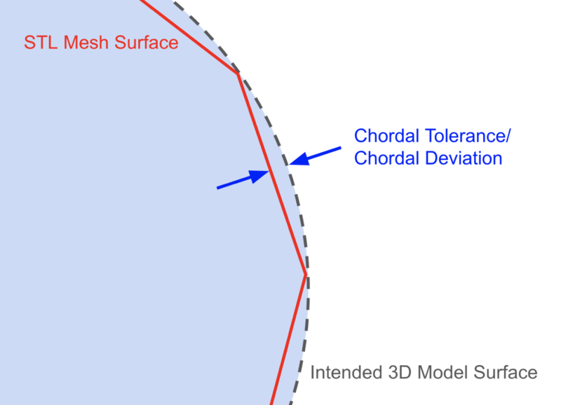
If a 3D print ends up with unwanted flat spots or jagged curves, the problem is almost always the STL file’s resolution, not your printer. You’re not the only one who has encountered this. We’ve received many questions from new users about faceted surfaces on their prints. To help everyone achieve the best results, this guide explains how to generate high‑resolution STL files that translate into smooth, dimensionally accurate parts. In this guide we cover: Read our latest customer success story about a major training base for the U.S. Army. TL;DR: Export your CAD geometry with the right STL resolution to achieve parts that are dimensionally accurate and surface‑smooth, without slowing down slicing. We recommend starting with these settings: If the file exceeds 20 MB, increase the chordal and/or angular tolerances until the size falls below 20 MB; large files can significantly slow slicer performance. If flat spots persist, reduce the tolerances while still keeping the file under 20 MB. The STL format, originally created for stereolithography in the 1980s, remains the industry standard for importing 3D models into slicers like Markforged’s Eiger. An STL file describes a mesh of triangles that approximates the surface of a 3D model. Each triangle is defined by three vertices and a normal vector perpendicular to the triangle’s plane. An ASCII STL lists each triangle in text form: Millions of such triangles build the mesh that can be imported into slicer software for printing. For 3D printing, the mesh must be manifold—each triangle edge shared by exactly two faces—to avoid gaps and errors during slicing. STL files from CAD programs typically meet this requirement, whereas files generated by 3D scanners may contain non‑manifold geometry. Since a triangle is a flat shape, a mesh can only perfectly reproduce geometries composed of flat surfaces. Curved surfaces—fillets, holes, organic shapes—are approximated by a collection of triangles, and the fidelity of that approximation depends on the STL export settings. If your prints meet your expectations and slicer performance is satisfactory, no change is necessary. However, low‑resolution STLs produce flat spots on curves, while excessively fine STLs inflate file size, lengthening slice times and potentially stalling the slicer UI. STLs lack unit information, so resolution must be inferred from the export settings. The most common issue is a coarse STL that fails to capture smooth geometry, resulting in visible faceting. Markforged’s Eiger software can help you spot low‑resolution STLs: when you hover over a part, the slicer highlights faces in blue. Clear facets indicate insufficient resolution; a smooth gradient suggests adequate fidelity. Conversely, an overly fine STL can inflate file size to the point where slicer performance degrades. Practical resolution rarely needs to be finer than the printer’s layer thickness; any additional detail is wasted time and storage. Follow best practices to balance print quality with workflow speed. Export settings influence the mesh density and, ultimately, the dimensional accuracy and surface finish of your print. Export parameters control the triangle density of the mesh. CAD software typically optimizes for the smallest file, but the parameters you specify can force a finer mesh where needed. Modern CAD packages expose at least two key export controls: chordal tolerance (linear) and angular tolerance (angular). Depending on geometry, one may dominate the mesh density. This parameter limits the maximum perpendicular distance between the original surface and the nearest triangle in the STL. A smaller chordal tolerance forces a finer mesh and increases file size. Angular tolerance limits the angle between normals of adjacent triangles, refining the mesh in regions of sharp curvature. When a fillet radius is comparable to the chordal tolerance, a low angular tolerance prevents visible faceting or unintended chamfers. When angular deviation is the limiting factor, the exporter adds more triangles around small radii, improving the smoothness of curved features beyond what chordal tolerance alone can achieve. Some CAD programs express angular control as a dimensionless value between 0 and 1; higher values increase resolution. Additional options—such as minimum or maximum facet length—are available in some CAD packages. Use them only if a specific feature requires it; otherwise, keep defaults. A higher‑resolution STL yields a smoother, more accurate model, but also increases file size, which can slow slicer processing. Most printers can’t exploit resolutions finer than the layer thickness, so the extra detail is unnecessary overhead. Start with the following balanced settings: If the resulting file exceeds 20 MB, increase the tolerances until the size drops below 20 MB. Experimentation is encouraged—your tolerance for size versus print quality may differ. Below are recommended starting points for popular CAD packages. Contact us if we’ve omitted a vendor or if your preferred settings differ. In Creo, the “Angle control” parameter refines angular deviation beyond the chord height. It ranges from 0.0 to 1.0. Suggested defaults:
U.S. Army Case Study

What Is an STL File?
facet normal ni nj nk
 outer loop
  vertex v1x v1y v1z
  vertex v2x v2y v2z
  vertex v3x v3y v3z
 endloop
endfacet
Why STL Files Matter for 3D Printing
Do I Need to Update My STL Files?
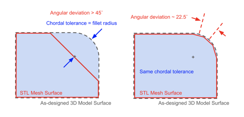
Defining STL Parameters
Chordal Tolerance / Deviation
Angular Tolerance / Deviation / Normal Deviation
Mesh Quality vs. File Size: Our Recommendations
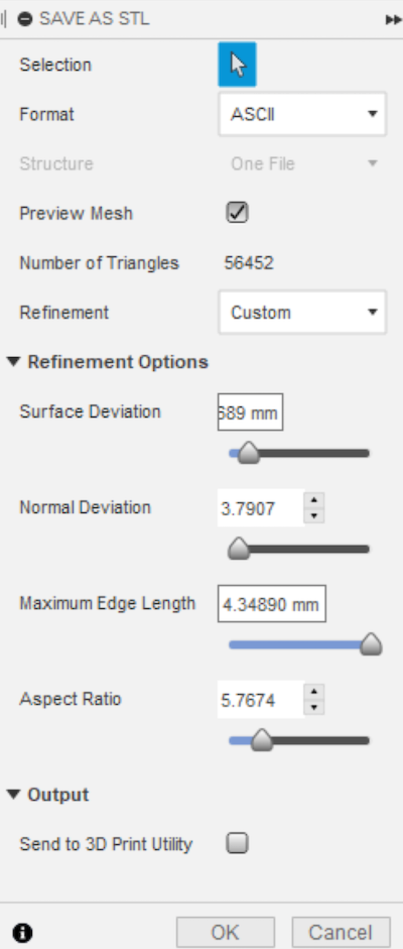
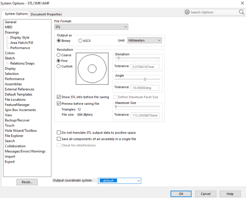
STL Export Settings in Major CAD Software
Creo (PTC)
Fusion 360 (Autodesk)
NX (Siemens)
Onshape (PTC)
SOLIDWORKS (Dassault Systèmes)
3D printing
- Maximizing the Potential of STL Files for Flawless 3D Printing
- Expert Thermoset Composite Tooling: Design, Durability, and Precision
- Creating Multi‑Body STL Files for Multi‑Material 3D Printing
- Understanding STL Files: The Backbone of 3D Printing
- Crafting High-Impact Content That Engages B2B Buyers in the Industrial Sector
- Master 3D Printing: A Complete Guide to Creating STL Models
- Top Trusted Sites for Free STL Downloads – 3D Printing Made Easy
- Step‑by‑Step Guide: Convert STL to G‑Code for Reliable 3D Printing
- Step-by-Step Guide to Creating STL Files for 3D Printing
- Effortlessly Serve Static Files with Go: A Proven Approach