


Differentiator Circuit – Visualizing the Rate of Change
PARTS AND MATERIALS
- Two 6 V batteries
- 0.1 µF capacitor (Radio Shack catalog #272‑135)
- 1 MΩ resistor
- Single‑turn, 5 kΩ linear potentiometer (Radio Shack catalog #271‑1714)
While any linear potentiometer will function, a lower‑resistance unit tends to provide a cleaner response. In practice I’ve used a 10 kΩ potentiometer with excellent results.
CROSS‑REFERENCES
Lessons In Electric Circuits, Volume 1, chapter 13: “Capacitors”
LEARNING OBJECTIVES
- Build a basic differentiator circuit.
- Gain a hands‑on understanding of the derivative as a rate of change.
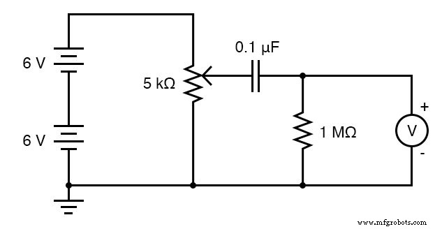
SCHEMATIC DIAGRAM
ILLUSTRATION
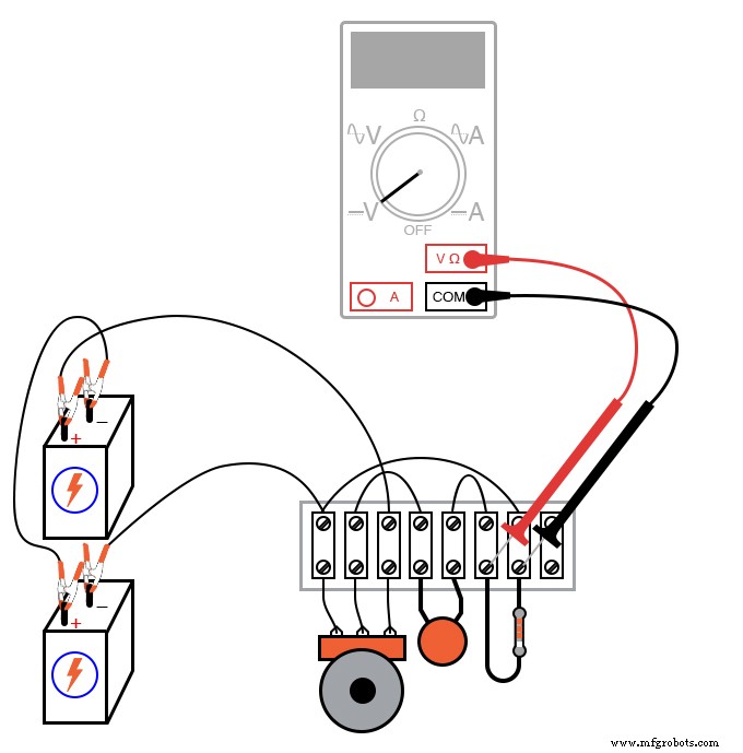
INSTRUCTIONS
Using the schematic, connect the potentiometer so that its wiper acts as the input voltage source. Measure the voltage between the wiper and the negative terminal of the lower 6‑V battery – this is your input. The input will sweep smoothly from 0 V to 12 V as the potentiometer is turned across its full range.
Next, attach a digital voltmeter across the 1 MΩ resistor. Set the meter to a millivolt range for maximum sensitivity. When the potentiometer is held steady, the meter should read zero (or a negligible offset). Slowly turn the potentiometer clockwise and note the voltage rise; then turn it counter‑clockwise and note the voltage drop. The sign of the voltage will change with the direction of motion, confirming that the circuit outputs the time‑derivative of the input signal.
Try adjusting the potentiometer so that the meter reads a steady, small voltage. The most stable readings occur when the potentiometer is moved at a constant rate—this produces a linear input voltage and a constant derivative.
This experiment demonstrates the core calculus concept of differentiation: the circuit’s output voltage is directly proportional to the instantaneous rate of change of the input voltage. Because the circuit performs a mathematical operation in real time, it functions as a simple analog computer. More sophisticated differentiators use op‑amps and RC networks to improve accuracy and bandwidth; for further study see the “Analog Integrated Circuits” chapter in this volume.
RELATED WORKSHEETS
- Passive Integrator and Differentiator Circuits Worksheet
Industrial Technology
- Circuit With a Switch: A Practical Guide to Basic Electrical Circuits
- Using a Potentiometer as a Rheostat for Simple Motor Speed Control
- Build a Precise, Low‑Cost Compound Potentiometer Circuit
- Voltage Follower Amplifier: Design, Build, and Measurement Guide
- Precision Op‑Amp Integrator Lab: Bias‑Current Compensation & Analog Computation
- Mastering AC Circuit Equations: Impedance, Reactance & Resonance
- Getting Started with SPICE: A Text‑Based Circuit Simulation Tool
- Mastering SPICE Netlist Syntax: Component Naming, Passive & Active Elements, and Source Definitions
- Hotel Bell Indicator Circuit – Comprehensive Hotelling Wiring Guide
- Potentiometer Wiring Made Easy: A Professional Guide