


Capacitor Charging & Discharging: A Hands‑On RC Circuit Experiment
Materials Needed for the Capacitor Charging & Discharging Experiment
To carry out the experiment, gather the following items:
- 6‑V battery
- Two electrolytic capacitors, 1 000 µF minimum (e.g., Radio Shack catalog #272‑1019, 272‑1032, or equivalent)
- Two 1 kΩ resistors
- One single‑pole, single‑throw (SPST) toggle switch (a household light switch works fine)
Large capacitance values are essential to achieve time constants long enough for accurate measurement with a voltmeter and a stopwatch.
Because most capacitors at these values are electrolytic, they are polarity sensitive. The negative terminal is usually marked with a line or series of lines pointing toward it; the positive terminal may have a + sign. Connecting a capacitor backwards will almost certainly cause it to fail, even at 6 V. Failed electrolytic capacitors can explode, releasing caustic chemicals and emitting a foul odor. Exercise caution.
Safety note: If you are unsure about the polarity markings, consult the datasheet or a qualified instructor.
Related Resources
- Lessons In Electric Circuits, Volume 1, Chapter 13: “Capacitors”
- Lessons In Electric Circuits, Volume 1, Chapter 16: “RC and L/R Time Constants”
Learning Objectives
After completing this lab you should be able to:
- Describe the charging behavior of a capacitor in an RC circuit.
- Describe the discharging behavior.
- Calculate the time constant τ = RC.
- Explain how series and parallel connections alter total capacitance.
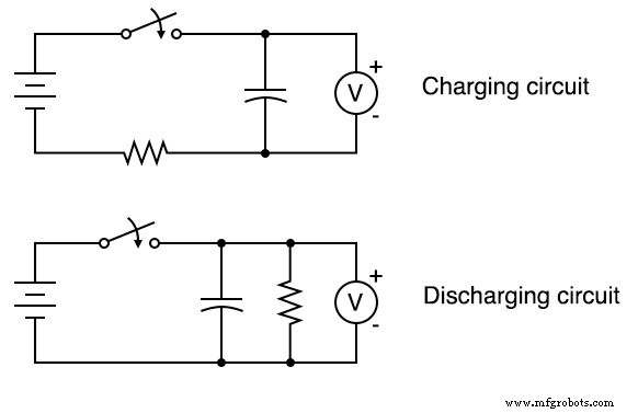
Charging and Discharging Circuit Schematic
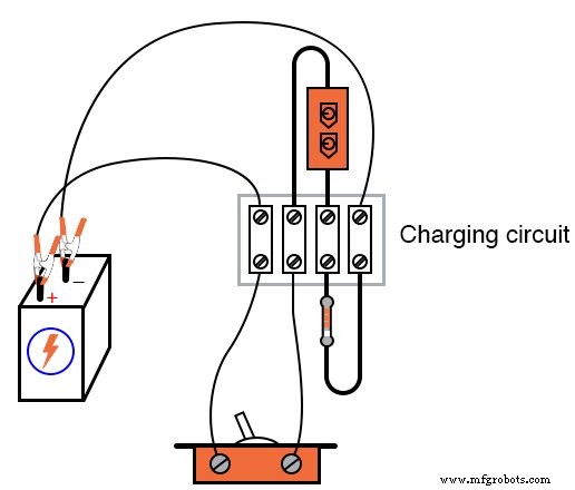
Experiment Setup
Procedure
Measuring Voltage During Charging
Assemble the charging circuit and close the switch. Use a voltmeter to record the voltage across the capacitor over time. Notice the gradual, exponential rise rather than a sudden jump.
To reset the capacitor to zero volts, short its terminals with a piece of wire.
The time constant τ of an RC circuit equals the product of resistance and capacitance. For a 1 kΩ resistor and a 1 000 µF capacitor, τ = 1 s. This is the time needed for the capacitor voltage to reach approximately 63.2 % of the battery voltage.
Plotting the voltage versus time on graph paper reveals the characteristic inverse‑exponential curve. A one‑second time constant offers limited resolution, so we can deliberately slow the circuit.
Modifying the Time Constant
Increase τ by adjusting:
- the total resistance (e.g., using more resistors in series), or
- the total capacitance (e.g., using capacitors in series or parallel).
Experiment with various series and parallel combinations of the two resistors and two capacitors to find the configuration that yields the slowest charging curve.
Remember: when connecting capacitors, ensure the negative leads are oriented toward the battery’s negative terminal.
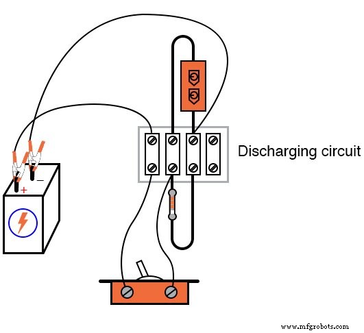
The discharging circuit behaves similarly, but the voltage starts at the battery level and decays slowly once the switch opens. Repeat the experiments with different resistor and capacitor arrangements, always respecting polarity.
Computer Simulation
SPICE schematic with node numbers:
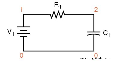
Netlist (copy the following text into a plain‑text file named rc.cir):
Capacitor charging circuit
v1 1 0 dc 6
r1 1 2 1k
c1 2 0 1000u
.ic 0
.tran 0.1 5
.uic
.plot tran v(2,0)
.end
Worksheets
- Time Constant Calculations Worksheet
- Capacitors Worksheet
Industrial Technology
- Tantalum Capacitors: Key Characteristics & Applications
- Calculating Voltage and Current in Reactive DC Circuits
- Mastering Java Date and Time: Constructors, Methods & Best Practices
- The Critical Role of Accurate Documentation in Engineering Success
- Comprehensive Guide to Date and Time in C++
- DIY Arduino PM10, Temperature & Humidity Sensor Kit
- Arduino Weather Clock – Real-Time Date, Time, Temperature & Humidity Display
- Effective Preparation and Charging of Blast Furnace Burden for Stable Operations
- Takt Time, Cycle Time, and Lead Time Explained: Key Definitions, Calculations, and Production Impact
- Capacitor Film 101: Properties, Build, and Practical Applications