


Understanding Negative Feedback in Op‑Amps: Voltage Followers and Stability
When the output of an operational amplifier is routed back to its inverting input while a signal is applied to the non‑inverting input, the device operates in a self‑correcting mode. In this configuration the op‑amp’s output tracks the input voltage almost exactly, thanks to negative feedback.
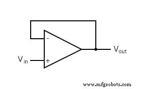
As the input voltage, Vin, rises, the output rises proportionally. However, because part of the output is fed back to the inverting input, the differential between the two inputs is continually reduced. The result is that the output settles at a voltage that keeps the differential nearly zero, a state of equilibrium that guarantees linear operation instead of saturation.
With a very high open‑loop gain, the voltage at the inverting input is virtually identical to Vin. The relationship can be expressed as:
$$V_{out} = G\cdot (V_{in} - V_{out})$$
Rearranging gives:
$$V_{out} = \frac{V_{in}}{1 + \frac{1}{G}}$$
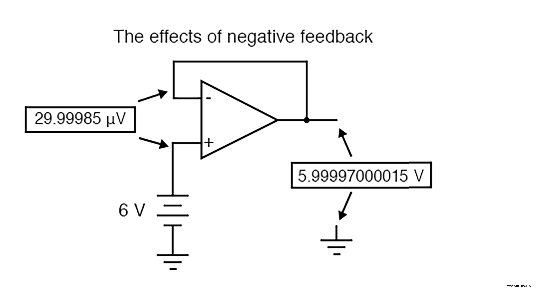
For example, an op‑amp with a differential gain of 200,000 driven by a 6 V input produces:
$$V_{out} = \frac{6}{1 + \frac{1}{200,000}} = 5.999700015\;\text{V}$$
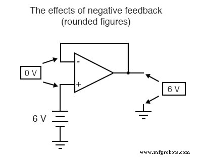
Only 29.99985 µV of differential voltage is needed to sustain this output, so for practical purposes the two input voltages are equal. The system therefore holds a stable state where the output closely matches the input.
Advantages of Negative Feedback
Negative feedback renders the exact open‑loop gain of the amplifier irrelevant. Whether the gain is 200,000 or 250,000, the output will remain virtually identical to the input. This self‑correcting property enables designers to build circuits with predictable, linear performance without needing to match the factory‑set gain precisely.
How the Op‑Amp Operates as a Voltage Follower
Inside the op‑amp, an internal “null detector” monitors the differential voltage. A highly sensitive internal potentiometer adjusts the output so that the detector reads zero volts. The result is a voltage follower (or buffer) that delivers the input voltage unchanged at its output, with a gain of 1.
Because the output is powered by the supply rails, the follower can source current to load the input without draining the input signal itself. Typical voltage followers provide high input impedance, low output impedance, and significant current gain, making them ideal for impedance matching and signal buffering.
Note that many classic op‑amps, such as the 741, cannot swing to the exact supply rails. With a ±15 V supply, a 741’s output typically tops out near +14 V and bottoms near –13 V due to its bipolar output stage. Modern rail‑to‑rail devices, like the 3130, can approach the supply rails within millivolts.
Review
- Connecting an op‑amp’s output to its inverting input implements negative feedback, a universal control strategy for achieving equilibrium.
- When the output is fed directly back to the inverting input, a voltage follower is formed, reproducing the non‑inverting input voltage at the output.
- Negative feedback forces the differential voltage to be practically zero; higher open‑loop gain makes the zero even tighter.
- Some op‑amps exhibit limited output swing, characterized by positive and negative saturation voltages.
Related Worksheet
Industrial Technology
- Common‑Emitter Amplifier: Design, Measurement, and Feedback Techniques
- Build a High‑Gain Differential Amplifier That Works as an Op‑Amp
- Precision Voltage Follower: Mastering Op‑Amp Feedback for Accurate Signal Tracking
- Digital Logic with Feedback: From Deterministic Gates to Multivibrators
- Integrating (Single‑Slope) ADCs: Principles, Advantages, and Dual‑Slope Alternatives
- Understanding Amplifier Feedback: Positive vs Negative, and Practical Applications
- How Voltage Dividers Set Gain in Non‑Inverting and Inverting Op‑Amp Amplifiers
- Positive Feedback in Op‑Amp Circuits: Hysteresis, Comparators, and Oscillators
- Tachogenerators: Precision Speed Measurement for Industrial Motors and Equipment
- Timers & Multi-Vibrators: Types, Functions, and Digital Applications