


Integrating (Single‑Slope) ADCs: Principles, Advantages, and Dual‑Slope Alternatives
While flash ADCs excel in speed, their large component count can be prohibitive for many designs. A common strategy to reduce complexity is to replace the DAC‑based ramp of a flash ADC with an analog integrator and a precise digital counter, yielding what is known as a single‑slope or integrating ADC.
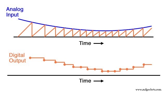
In this architecture, an op‑amp integrator generates a continuous sawtooth waveform. The analog input is compared against this ramp by a high‑speed comparator. The instant the comparator’s output toggles indicates that the integrator voltage has matched the input, and the time elapsed is captured by a counter driven by a crystal‑oscillator clock.
The schematic below illustrates the core block diagram:
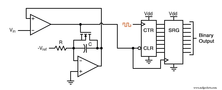
The diagram simplifies the IGFET‑based discharge transistor; in practice a latching circuit tied to the clock ensures the capacitor fully discharges when the comparator goes high.
During a conversion, the comparator output is low while the input exceeds the integrator output. The integrator then charges the capacitor linearly, and the counter increments at the fixed clock rate. When the capacitor voltage equals the input, the comparator flips high, latching the counter value into a shift register and triggering the IGFET to discharge the capacitor to zero.
Once the integrator voltage falls back to zero, the comparator switches low again, clearing the counter and allowing the next conversion to begin. In effect, the single‑slope ADC behaves like a digital‑ramp ADC, but with a smooth sawtooth reference instead of a stepwise one.
Despite eliminating the DAC, the single‑slope architecture suffers from calibration drift. Because the conversion accuracy depends on the exact match between the integrator’s slope (set by –Vref, R, and C) and the counter’s clock rate, any drift in either parameter degrades performance. Unlike the digital‑ramp ADC, where the clock only affects update time, the interdependence of integration and counting makes the single‑slope ADC vulnerable to aging and temperature variations.
However, the reduced component count and simplified layout can be attractive for low‑cost, low‑power applications.
This ADC circuit behaves very much like the digital ramp ADC, except that the comparator reference voltage is a smooth sawtooth waveform rather than a “stairstep”.
Dual‑Slope Converter
The dual‑slope ADC resolves the calibration drift problem by employing two integration phases. In the first phase, the integrator charges with the unknown input for a fixed time interval measured by the counter. In the second phase, the integrator discharges with a known reference voltage at a constant rate; the time required to return to the starting voltage is counted.
The ratio of the two time intervals directly yields the digital value, and because both integration and counting occur during the same cycle, any change in the clock frequency cancels out. A faster clock shortens the fixed‑time phase but also speeds up the discharge counting, leaving the final result unchanged.
Moreover, the averaging inherent in the integration phase makes dual‑slope converters highly immune to transient noise. By summing the input over the integration window, spikes and dips are smoothed out, which is why dual‑slope ADCs are common in precision measurement instruments such as multimeters and energy meters.
In summary, while the single‑slope ADC offers a simpler design, the dual‑slope architecture provides superior accuracy and noise immunity at the cost of a longer conversion time.
RELATED WORKSHEET:
- Analog‑to‑Digital Conversion Worksheet
Industrial Technology
- Common‑Emitter Amplifier: Design, Measurement, and Feedback Techniques
- Build a High‑Gain Differential Amplifier That Works as an Op‑Amp
- Precision Voltage Follower: Mastering Op‑Amp Feedback for Accurate Signal Tracking
- Flash ADC (Parallel Analog‑to‑Digital Converter) – Design, Operation, and Applications
- Digital Ramp (Counter) ADC: Operation, Benefits, and Limitations
- Tracking ADC: Up/Down Counter for Fast, Continuous Signal Conversion
- Delta‑Sigma ADC: Harnessing Oversampling for Precise Analog‑to‑Digital Conversion
- Understanding Negative Feedback in Op‑Amps: Voltage Followers and Stability
- Positive Feedback in Op‑Amp Circuits: Hysteresis, Comparators, and Oscillators
- Timers & Multi-Vibrators: Types, Functions, and Digital Applications