


Lever Analogy: Clarifying Divided Feedback in Amplifiers
To demystify divided‑feedback amplifier circuits, we can turn to a familiar mechanical system: a lever. The lever’s moving ends represent input and output voltages, while the pivot—whether a physical ground or a virtual one—acts as the feedback reference.
Consider the classic non‑inverting op‑amp shown below. As discussed earlier, its voltage gain can never fall below unity. By pairing a lever diagram with the schematic—where the lever’s arm lengths correspond to the resistor values—we can visualise how voltage changes translate into mechanical displacement.
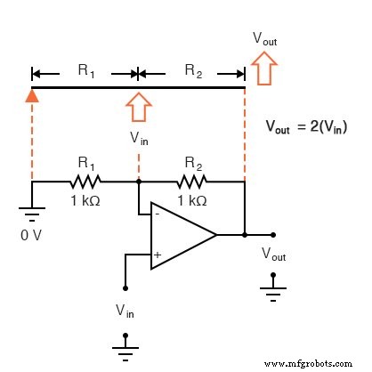
Physicists label this arrangement a third‑class lever, because the effort (input) and load (output) lie on the same side of the fulcrum. Third‑class levers exhibit an output displacement that is at least as large as the input, matching the ≥1 gain of the non‑inverting amplifier.
Pushing the input point upward on the lever is analogous to applying a positive input voltage. The lever’s geometry amplifies the motion: the output point moves twice as far and in the same direction. In the circuit, the output voltage equals twice the input, preserving polarity.
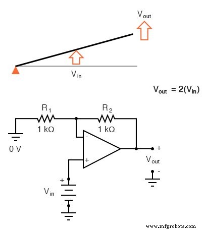
Due to the displacement‑amplifying characteristics of the lever, the “output” point will move twice as far as the “input” point, and in the same direction. In the electronic circuit, the output voltage will equal twice the input, with the same polarity. Applying a negative input voltage is analogous to moving the lever downward from its level “zero” position, resulting in an amplified output displacement that is also negative:
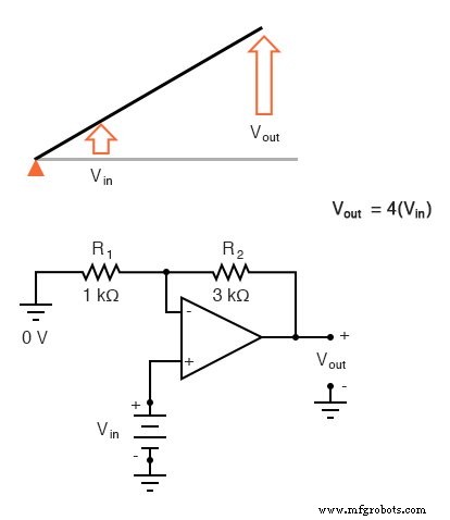
Changing the resistor ratio R₂/R₁ repositions the input point relative to the fulcrum, thereby adjusting the mechanical gain. For instance, increasing R₂ relative to R₁ shifts the lever so that the output displacement becomes four times the input.
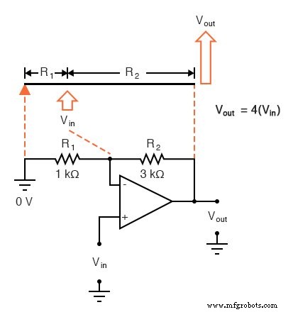
Now, any input signal will become amplified by a factor of four instead of by a factor of two:
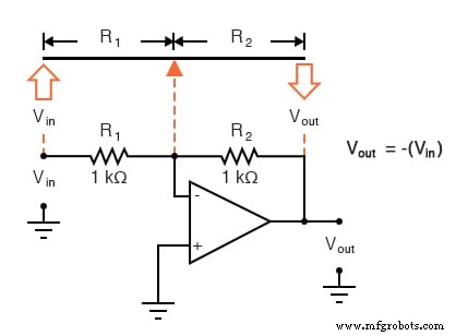
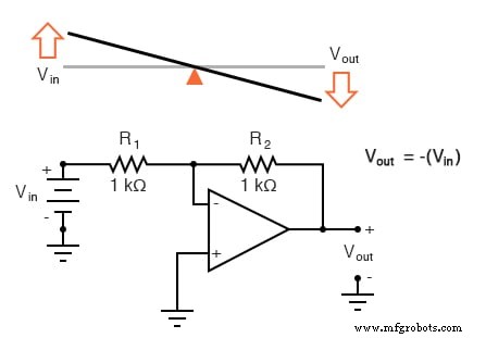
Inverting configurations can be mapped onto the lever analogy as well, but with a different mechanical class. Here the ground point of the feedback divider is the op‑amp’s inverting input, placing the input on one side of the fulcrum and the output on the other—a first‑class lever.
When the two resistors are equal—mirroring equal lever lengths on either side—the output displacement equals the input magnitude but reverses direction. Thus a positive input produces a negative output.
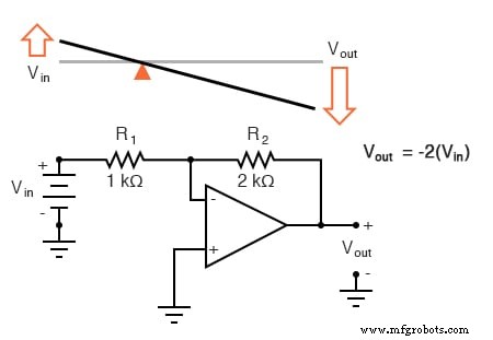
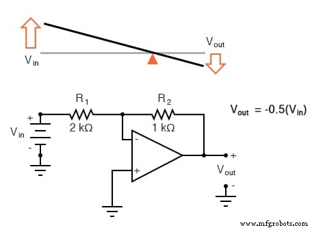
Adjusting R₂/R₁ again shifts the lever’s fulcrum, modulating the gain. If R₂ is twice R₁, the lever’s geometry yields a gain of –2. Conversely, swapping the resistor values moves the fulcrum one‑third of the way from the output end, giving a gain of –½.
Industrial Technology
- Connext DDS Users Group in Chengdu: Real Feedback Drives Our Roadmap
- Non‑Inverting Amplifier: Build, Test, and Master Op‑Amp Gain Control
- Using the 4511 7‑Segment Decoder: A Practical BCD Display Tutorial
- Mastering the D Latch: A Clean 1‑Bit Memory Circuit
- Understanding Amplifier Feedback: Positive vs Negative, and Practical Applications
- How Voltage Dividers Set Gain in Non‑Inverting and Inverting Op‑Amp Amplifiers
- Ohm’s Law Explained: A Water‑Pipe Analogy for Clear Intuition
- Build an Isolated Analog Input Circuit for Arduino
- PCB Manufacturing in the Era of 5G: Trends & Challenges
- Enhancing CNC Program Precision with External Input Integration