


Phase Rotation in Three‑Phase Alternators: Mechanics, Detection, and Wire Reversal
Three‑Phase Alternator
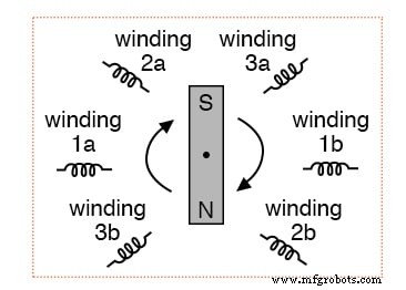
Let’s revisit the three‑phase alternator design we discussed earlier and observe the effects of magnet rotation on the generated voltages.
Three‑phase alternator
The 120° phase shift is a direct result of the actual angular displacement of the three winding pairs. If the magnet turns clockwise, winding 3 reaches its voltage peak 120° of shaft rotation after winding 2, which itself peaks 120° after winding 1. The magnet passes each pole pair at distinct shaft angles.
The placement of the windings determines the phase shift between the AC waveforms of each winding. Using winding 1 as a reference (0°), winding 2 is –120° (or +240°) and winding 3 is –240° (or +120°).
Phase Sequence
Clockwise shaft rotation produces a repeatable sequence: 1 → 2 → 3. The sequence persists as long as the alternator continues to spin.
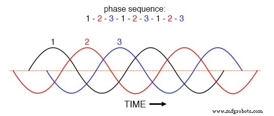
Clockwise rotation phase sequence: 1‑2‑3.
Reversing the shaft direction (counter‑clockwise) swaps the order to 3 → 2 → 1. In this case, winding 2 leads winding 1 by 120°, and winding 3 leads winding 2 by another 120°.
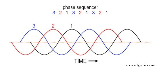
Counter‑clockwise rotation phase sequence: 3‑2‑1.
The arrangement of voltage waveforms in a polyphase system is called phase rotation or phase sequence. For purely resistive loads, the sequence makes no difference—magnitudes remain identical regardless of 1‑2‑3 or 3‑2‑1. However, certain three‑phase applications, especially those involving unbalanced reactive loads, are sensitive to the direction of phase rotation.
Phase Sequence Detectors
Standard voltmeters and ammeters cannot reveal the sequence of a live power system. Instead, a simple detector circuit employs a capacitor to introduce a phase shift between voltage and current, which then manifests as a difference in the brightness of two indicator lamps.
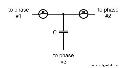
Phase sequence detector compares the brightness of two lamps.
Both lamps have identical filament resistance and wattage. The capacitor is sized to provide a reactance roughly equal to each lamp’s resistance at the system frequency. Replacing the capacitor with a resistor of equal value would balance the circuit, yielding equal lamp brightness. The capacitor, however, introduces a 90° phase shift in the third leg, skewing the voltage and current seen by the lamps based on their relative phase offsets.
SPICE Analysis for Phase Sequence Detectors
The following SPICE simulation, labeled phase rotation detector – sequence = v1‑v2‑v3, illustrates the effect of a 90° phase shift.
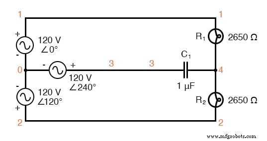
SPICE circuit for phase sequence detector.
phase rotation detector -- sequence = v1-v2-v3
v1 1 0 ac 120 0 sin
v2 2 0 ac 120 120 sin
v3 3 0 ac 120 240 sin
r1 1 4 2650
r2 2 4 2650
c1 3 4 1u
.ac lin 1 60 60
.print ac v(1,4) v(2,4) v(3,4)
.end

freq          v(1,4)      v(2,4)      v(3,4)
6.000E+01     4.810E+01   1.795E+02   1.610E+02
The capacitor’s phase shift reduces the voltage across the first lamp to 48.1 V while raising the second lamp’s voltage to 179.5 V, causing the first lamp to dim and the second to brighten. Reversing the phase sequence (i.e., phase rotation detector – sequence = v3‑v2‑v1) inverts the result: the first lamp becomes bright and the second dim.
phase rotation detector -- sequence = v3-v2-v1
v1 1 0 ac 120 240 sin
v2 2 0 ac 120 120 sin
v3 3 0 ac 120 0 sin
r1 1 4 2650
r2 2 4 2650
c1 3 4 1u
.ac lin 1 60 60
.print ac v(1,4) v(2,4) v(3,4)
.end

freq          v(1,4)      v(2,4)      v(3,4)
6.000E+01     1.795E+02   4.810E+01   1.610E+02
Thus, phase rotation is governed by the order in which the alternator’s rotating magnet passes pole pairs, and reversing the shaft direction alters that order. In practice, end‑users cannot reverse the rotation of the national grid’s combined alternators, but they can achieve the same effect by swapping any two of the three hot wires supplied to a three‑phase load.
Exchanging Hot Wires
Swapping two hot wires is a straightforward method to reverse phase sequence. Consider a running 1‑2‑3 rotation: 1‑2‑3‑1‑2‑3‑… Reversing the sequence to 3‑2‑1 is equivalent to swapping any two wires. The result is always a reversed order (e.g., 2‑1‑3, 1‑3‑2, or 3‑2‑1).
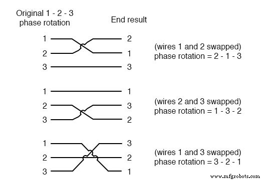
All possibilities of swapping any two wires.
Review
- Phase rotation (or phase sequence) refers to the order in which the voltage waveforms of a polyphase AC source reach their peaks. For a three‑phase system, only two sequences exist: 1‑2‑3 and 3‑2‑1, corresponding to the two possible directions of alternator rotation.
- Phase rotation has no impact on purely resistive loads but affects unbalanced reactive loads, as demonstrated by the phase rotation detector circuit.
- Reversing phase sequence can be accomplished by swapping any two of the three hot leads feeding a three‑phase load.
Related Worksheets
Industrial Technology
- Low‑Voltage AC Power Supply: Phase‑Shift Circuit Components & Best Practices
- Sequences: Understanding Arithmetic and Geometric Progressions
- Understanding Four‑Bit Binary Counters
- Phase Shift Oscillator & Varactor Multipliers: Design Principles & Applications
- Understanding AC Phase Shift: How Waveforms Lead and Lag
- Representing AC Voltages and Currents as Vectors
- Vector Addition and AC Voltage Superposition: A Practical Guide
- Designing Polyphase AC Motors: Fundamentals and Practical Startup Techniques
- Understanding Harmonic Phase Sequences in Three-Phase Power Systems
- Measuring Frequency and Phase in AC Power Systems