


Δ‑Y and Y‑Δ Conversions: Expert Guide for Circuit Analysis
In many practical circuits, components are arranged as either a Δ (delta) or a Y (wye) network. These configurations are ubiquitous in power systems, signal processing, and network design.
By determining the appropriate resistor values, a Δ network can be made electrically indistinguishable from a Y network when examined solely at their three terminals (A, B, and C). This equivalence allows engineers to replace one topology with the other without altering circuit behavior.
Δ‑Y and Y‑Δ Conversion Equations
The standard formulas for converting between Δ and Y are:
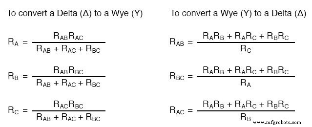
These equations are particularly useful when working with unbalanced or asymmetric networks, such as in three‑phase power systems where the Δ and Y forms may not be perfectly balanced.
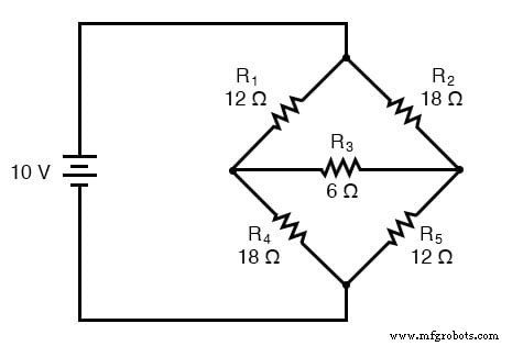
Practical Application: Unbalanced Bridge Circuits
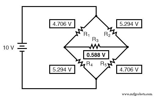
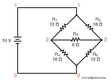
One of the most common scenarios requiring Δ‑Y conversion is the analysis of an unbalanced bridge circuit:
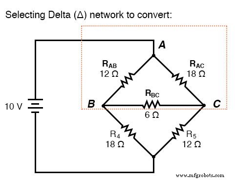
Traditional mesh or node‑voltage methods become cumbersome, and techniques like Millman’s or superposition offer limited help because the bridge has only a single power source. By converting the Δ‑connected resistors (R₁, R₂, R₃) to an equivalent Y network, the bridge simplifies to a combination of series and parallel resistances, making voltage and current calculations straightforward.
After the Δ‑Y conversion:
Continuing the analysis yields the following key voltage drops:
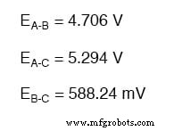
Resistors R₄ and R₅ remain unchanged at 18 Ω and 12 Ω, respectively. Solving the simplified series/parallel network gives the voltage distribution across all nodes.
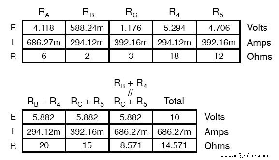
These voltages can then be mapped back onto the original bridge, providing the same node potentials:
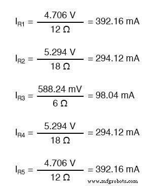
Finally, Ohm’s law (I = V / R) yields the individual currents through each resistor.
Verification with SPICE Simulation
To confirm the analytical results, the following SPICE netlist models the unbalanced bridge:
unbalanced bridge circuit
v1 1 0
r1 1 2 12
r2 1 3 18
r3 2 3 6
r4 2 0 18
r5 3 0 12
.dc v1 10 10 1
.print dc v(1,2) v(1,3) v(2,3) v(2,0) v(3,0)
.end
v1          v(1,2) v(1,3)    v(2,3)      v(2)         v(3)
1.000E+01   4.706E+00 5.294E+00 5.882E-01   5.294E+00    4.706E+00
The printed voltages match the analytical predictions, validating the Δ‑Y conversion formulas.
Review- Δ (Delta) networks are also called π (Pi) networks.
- Y (Wye) networks are also known as T networks.
- Using the correct resistance equations, Δ and Y networks can be interconverted so they are electrically identical at their three terminals.
- By converting part of an unbalanced bridge from Δ to Y, the circuit reduces to a simple series/parallel network; the solved node voltages can then be transferred back to the original bridge.
- Delta and Wye 3‑Phase Circuits Worksheet
Industrial Technology
- Wire Connection Conventions in Electrical Schematics: A Clear Guide
- Decoding Numbers and Symbols in Electronics
- Minterms & Maxterms in Karnaugh Maps: Clear Notation & Practical Examples
- Understanding Electrons, Holes, and Doping in Semiconductors
- Understanding Series and Parallel Capacitors: How Capacitance Adds or Diminishes
- Analyzing a Parallel R‑L‑C Circuit: Impedance, Current, and SPICE Simulation
- Analyzing Series-Parallel RC and RL Circuits with Complex Impedance
- Comprehensive Summary of Resistors, Inductors, and Capacitors in AC Circuits
- Automatic Star-Delta Starter with Timer: 3-Phase AC Motor Power, Control & Wiring Diagram
- Harnessing Automation in Manufacturing: Boost Efficiency & Cut Labor Costs